


Next: Summing amplifier
Up: Building circuits with op-amps
Previous: Current-to-voltage converter
As seen in Section 3.1, the input offset voltage of op-amps can introduce
significant output errors. Many op-amps (351, 741) have additional pins for
adjusting the offset to zero.
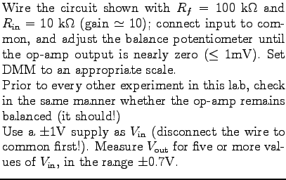
![$\textstyle \parbox{2.0in}{\raisebox{-2.5in}{\par
\hbox{\hskip 0in \vbox to 2.5in{\includegraphics[height=2.5in]{FIGS/fig3.3.ps}\vfill}}}}$](img64.png)
 |
Calculated  |
Measured |
% error |
| |
|
|
|
| |
|
|
|
| |
|
|
|
| |
|
|
|
| |
|
|
|
- Use the FG set at 1 kHz as
 . Use the two channels of the scope to
monitor the inverting input of the op-amp and . Slowly increase the
amplitude of the input signal, starting near zero. Observe what happens at the
inverting input as the amplifier saturates. Is the assumption of virtual
ground still valid?
. Use the two channels of the scope to
monitor the inverting input of the op-amp and . Slowly increase the
amplitude of the input signal, starting near zero. Observe what happens at the
inverting input as the amplifier saturates. Is the assumption of virtual
ground still valid?
- Keeping the amplitude of the input low and constant, vary its frequency.
Can you estimate the maximum slew rate of the 351?
Next: Summing amplifier
Up: Building circuits with op-amps
Previous: Current-to-voltage converter
For info, write to: physics@brocku.ca
Last revised: 2007-01-05