next up previous contents
Next: Op-amp differentiator Up: Advanced op-amp designs Previous: Advanced op-amp designs

Op-amp integrator

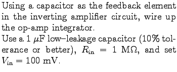
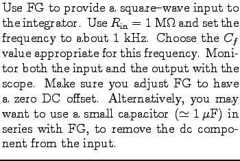
The purpose of this section is to wire up and analyze an analog integrator, using a carefully balanced op-amp and a low-leakage quality capacitor. We will observe the circuit response to both dc input signals and to the ac waveforms generated by the FG.

$\textstyle \parbox{2.0in}{\raisebox{-1.5in}{\par
\hbox{\hskip 0in \vbox to 1.5in{\includegraphics[height=1.5in]{FIGS/fig4.1.ps}\vfill}}}}$ $\textstyle \parbox{3.0in}{%
Using a capacitor as the feedback element in the in...
...rance or better),
$R_{\rm in} = 1$ M$\Omega$, and set $V_{\rm in} = 100$ mV.
}$
Measure the times required for the output to change by 1V, 3V, 5V, and 8V. Begin the timing when the touch jumper is removed. Use the jumper to discharge the integrating capacitor, i.e. to restart the integrator. Repeat 1V measurement at least 3 times, estimate the precision of your measurements (standard deviation).

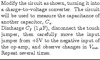
The above measurements require that the op-amp be well-balanced. To test, restart the integrator, and quickly remove $V_{\rm in}$ when $V_{\rm
out} \simeq 1$V. Does $V_{\rm out}$ remain constant after that? If not, re-balance the op-amp.

Connect the input to ground, reset the integrator, and observe $V_{\rm out}$ on the most sensitive DMM scale. Record your observations.

$\textstyle \parbox{2.0in}{\raisebox{-1.5in}{\par
\hbox{\hskip 0in \vbox to 1.5in{\includegraphics[height=1.5in]{FIGS/fig4.2.ps}\vfill}}}}$ $\textstyle \parbox{3.0in}{%
Modify the circuit as shown, turning it into a char...
...he op-amp, and observe changes in \mbox{$V_{\rm out}$}. Repeat several
times.
}$
Compare the measured value of the ratio $C_{f}/C_{x}$ with that obtained by a direct reading of the capacitance meter.

$\textstyle \parbox{2.0in}{\raisebox{-1.5in}{\par
\hbox{\hskip 0in \vbox to 1.5in{\includegraphics[height=1.5in]{FIGS/fig4.3.ps}\vfill}}}}$ $\textstyle \parbox{3.0in}{%
Use FG to provide a square-wave input to the integ...
...simeq 1 \mu$F) in series with FG, to remove the dc component from the input.
}$
Sketch and explain the observed waveforms.


next up previous contents
Next: Op-amp differentiator Up: Advanced op-amp designs Previous: Advanced op-amp designs

For info, write to: physics@brocku.ca
Last revised: 2007-01-05