next up previous contents
Next: Difference amplifier Up: Advanced op-amp designs Previous: Op-amp integrator

Op-amp differentiator

By interchanging the resistor and capacitor of the op-amp integrator, we obtain an op-amp differentiator. We will analyze its response to various waveforms of the FG.

Do not remove the circuit of the previous section; you may want to re-use it in Section 4.3.
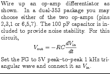
$\textstyle \parbox{2.0in}{\raisebox{-1.5in}{\par
\hbox{\hskip 0in \vbox to 1.5in{\includegraphics[height=1.5in]{FIGS/fig4.4.ps}\vfill}}}}$ $\textstyle \parbox{3.0in}{%
Wire up an op-amp differentiator as shown. In a dua...
...V peak-to-peak 1 kHz triangular wave and connect it as \mbox{$V_{\rm in}$}.
}$
Sketch the input and output waveforms, including the proper scales. Make sure your scope is on a calibrated setting.

Calculate and record the slope of the input triangular wave. Also, record the amplitude of the square wave at the output.

Calculate the expected theoretical value for the differentiator output and compare it to the experimental value.

Change the FG to square wave setting. Sketch the observed waveforms.


For info, write to: physics@brocku.ca
Last revised: 2007-01-05