


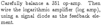
Using a non-linear feedback element with an op-amp (e.g. a pn-junction diode) produces startlingly different transfer functions. Logarithmic amplifiers serve as the basis for circuits such as analog multipliers studied in Section 4.6.
![$\textstyle \parbox{2.0in}{\raisebox{-1.25in}{\par
\hbox{\hskip 0in \vbox to 1.25in{\includegraphics[height=1.25in]{FIGS/fig4.7.ps}\vfill}}}}$](img98.png)
| 10.0mV | 1M |
||
| 10.0mV | 100k |
||
| 100.0mV | 100k |
||
| 1.0V | 100k |
||
| 10.0V | 100k |
||
| 10.0V | 10k |
For all but very small forward bias voltages, the current through a diode varies
exponentially with the applied voltage:
Apply circuit analysis (Simpson, Sec. 9.7) to your logarithmic amplifier
and verify that the same
relationship holds for the measured ![]() and
and ![]() .
.
Fit your data to the above equation and determine the parameters ![]() and
and ![]() for your diode. Can you tell if this is a Si or a Ge diode?
for your diode. Can you tell if this is a Si or a Ge diode?
For info, write to: physics@brocku.ca