next up previous contents
Next: Using microcomputers in a physics Up: Active filters and tuned amplifiers Previous: Notch filter

Lock-in amplifier

One of the best ways to dicriminate against noise is to use a lock-in amplifier. It combines the techniques of signal modulation at the source, band-pass limitation, and phase-lock demodulation to provide ability to distinguish weak signals ``buried'' in the noise. Because they actively modulate the source signal, lock-in amplifiers are capable of distinguishing signal and noise that have overlapping frequency spectra.

$\textstyle \parbox{2.5in}{\raisebox{-2.1in}{\par
\hbox{\hskip 0in \vbox to 2.1in{\includegraphics[height=2.1in]{FIGS/fig5.4.ps}\vfill}}}}$ $\textstyle \parbox{2.5in}{%
Connect a biased photodiode or a photo\-transistor ...
...til the
square-wave component of 50 to $100 $mV is obtained at the output.
}$

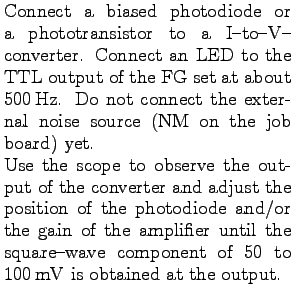
Make note of the DC level, the square-wave amplitude (p-p), and the approximate noise amplitude (p-p) in the output signal.

Why is there a DC component in the output of the I-to-V-converter?

$\textstyle \parbox{\textwidth}{\par
\hbox{\hskip -0.15in \vbox to 2.0in{\includegraphics[height=2.0in]{FIGS/fig5.5.ps}\vfill}}}$

Now connect the AF100 tuned amplifier circuit to the output of the I-to-V converter. Observe the tuned amplifier output with the scope. Adjust the FG frequency to get the maximum output from the tuned amplifier. Record your values of tuned amplifier output voltage (p-p), waveshape appearance, DC component of the output voltage, and the FG frequency setting.

You should have observed a sine wave at the tuned amplifier output. The input, however, was a noisy square wave with a DC component. Explain the difference in input and output waveforms.

The analog multiplier and low pass filter (phase-locked demodulator) should now be connected. The tuned amplifier output is multiplied by a square wave that is synchronous with the LED modulation. Adjust the FG square wave output to supply a $\pm 10 $V reference signal to the multiplier. Observe the multiplier output. Adjust the FG frequency carefully to obtain a waveform that most closely approximates a full-wave rectified sine wave. Draw the observed multiplier output waveform. Label the axes.

Connect the active low-pass filter to the multiplier output. Observe the DC output with the scope. Record the DC level observed with the modulated LED on and off.

Look again at the I-to-V converter output and measure the ratio of the square-wave amplitude to noise amplitude.

Calculate the signal-to-noise (S/N) ratio improvement obtained with the lock-in amplifier.

To better demonstrate the noise rejection capabilities of the lock-in amplifier, still more noise will be intentionally added to the signal. This noise will be obtained from the noise generator circuit available on the reference job board.

$\textstyle \parbox{2.5in}{\raisebox{-2.in}{\par
\hbox{\hskip 0in \vbox to 2.in{\includegraphics[height=2.in]{FIGS/fig5.6.ps}\vfill}}}}$ $\textstyle \parbox{2.5in}{%
The relevant part of the reference job board circui...
...led into a summing amplifier
that also serves as an active low-pass filter.
}$

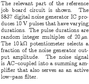
The additional input to the summing amplifier allows the noise generator signal to be added to another signal: $ V_{\rm NM} = \mbox{$V_{\rm in}$}+ {\rm noise} $

Vary the $10 $k$\Omega$ potentiometer to obtain maximal noise amplitude. Sketch the waveform observed on both sides of the coupling capacitor and at the output of the summing amplifier. An oscilloscope time base of 20$ \mu$s/div is recommended.

Also observe the output of the summing amplifier at a sweep speed of 500$ \mu$s/div. This output is labelled NM on the job board, for Noise Mixer output.

Calculate the cut-off frequency of the low-pass filter in the NM. What is the attenuation of this filter for the frequency component that results from transitions every 20$ \mu$s (25kHz)?

Connect the NM output through a $100 $k $\mbox{$\Omega$}$ resistor to the summing point of the I-to-V converter (in the noisy signal source). Observe the converter output with a scope and adjust the noise generator output from zero until the square wave becomes difficult to see. (Trigger the scope from a clean square-wave or TTL output of the FG to avoid loss of synch.) Measure the DC output voltage of the lock-in amplifier, with the modulated LED on and then off. Compare again the signal-to-noise (S/N) ratios at the input and output of the lock-in amplifier.

Explain why it is necessary to modulate the signal in order to obtain the improvement in S/N through the lock-in technique.


next up previous contents
Next: Using microcomputers in a physics Up: Active filters and tuned amplifiers Previous: Notch filter

For info, write to: physics@brocku.ca
Last revised: 2007-01-05