PHYS 2.8: Angular momentum |
PPLATO @ | |||||
PPLATO / FLAP (Flexible Learning Approach To Physics) |
||||||
|
1 Opening items
1.1 Module introduction
The aim of this module is to explore the general principles governing rotational motion. We will explain why, for example, a spinning skater rotates more quickly when her arms are pulled in closer to the axis of rotation, and why a falling diver spins faster when he curls up. It turns out that the principles that are at work here also give insights into the orbital motion of the planets and the ability of some stars, the pulsars, to behave as rapidly pulsating sources of light. This module considers general types of rotation. In particular, we will investigate why a rotating object, such as a gyroscope, displays a surprising degree of stability. These and other phenomena will be interpreted in terms of the concept of rotational or angular momentum and its conservation under certain conditions.
Section 2 will review the general features of uniform circular motion, concentrating on quantities that do not change with time (the so–called constants of the motion) and introducing the angular velocity vector. Section 3 is a brief mathematical interlude which reviews the use of unit vectors and vector products. In Section 4 the concepts of angular momentum, moment of inertia and torque are introduced and the analogies with translational motion explored. Newton’s second law of motion is then extended to rotational dynamics and the principle of angular momentum conservation is introduced. In Section 5 a number of specific examples are discussed in terms of the conservation of angular momentum; these include the motion of the planets around the Sun, rotating dumb-bells, gyroscopes and helicopters.
Study comment Having read the introduction you may feel that you are already familiar with the material covered by this module and that you do not need to study it. If so, try the following Fast track questions. If not, proceed directly to the Subsection 1.3Ready to study? Subsection.
1.2 Fast track questions
Study comment Can you answer the following Fast track questions? If you answer the questions successfully you need only glance through the module before looking at the Subsection 6.1Module summary and the Subsection 6.2Achievements. If you are sure that you can meet each of these achievements, try the Subsection 6.3Exit test. If you have difficulty with only one or two of the questions you should follow the guidance given in the answers and read the relevant parts of the module. However, if you have difficulty with more than two of the Exit questions you are strongly advised to study the whole module.
Question F1
A freely rotating polished turntable of radius 2.0 m and mass 200 kg rotates in a horizontal plane about its central axis at 14 revolutions per minute. A girl of mass 50 kg steps on to the turntable at distance of 1.0 m from the axis of rotation. She slides on the turntable and only stops sliding when she grasps a rail on the extreme edge of the turntable, 2.0 m from the axis of rotation. Find (a) the angular speed of the turntable and girl after she stops sliding; (b) the amount of energy dissipated during the process. (You may ignore friction at the axle of the turntable. The moment of inertia of a homogeneous disc of mass M and radius a about its central axis is $I=\frac{1}{2}Ma^2$.)
Answer F1
When the girl steps onto the turntable she experiences a frictional force on her feet. This force has both radial and tangential components. The tangential component gives the girl an increasing angular speed. The radial component provides the centripetal force needed to keep the girl in circular motion. Before the girl has reached the same angular speed as the wheel, the frictional force has achieved its maximum possible value; since there is insufficient centripetal force to maintain the girl in a circular orbit she drifts outwards until she reaches the rim.
(a) We need no details of the forces to use the principle of angular momentum conservation for the whole system to predict the final common angular speed. Angular momentum conservation is applicable because there is no external torque about the axis of rotation. The moment of inertia of the disc is I and its initial angular speed is ω1; the final moment of inertia of the disc plus girl (mass m at distance r from the axis) is (I + mr2) and the final common angular speed is ω2. Angular momentum conservation gives:
Iω1 = (I + mr2)ω1
so$\omega_2=\omega_1\left(\dfrac{I}{I+mr^2}\right) = \omega_1\left(\dfrac{\frac{1}{2}Ma^2}{\frac{1}{2}Ma^2+mr^2}\right) = 2\pi\times \dfrac{14}{60}\,{\rm rad\,s^{-1}}\left(\dfrac{\frac{1}{2}\times 200\,{\rm kg}\times 4\,{\rm m^2}}{\frac{1}{2}\times 200\,{\rm kg}\times 4\,{\rm m^2}+50\,{\rm kg}\times 4\,{\rm m^2}}\right) = 0.977\,{\rm rad\,s^{-1}}$
This can be compared with the initial angular speed
$\dfrac{2\pi\,{\rm rad\,rev^{-1}}\times 14\,{\rm rev\,min^{-1}}}{60\,{\rm min^{-1}}} = 1.47\,{\rm rad\,s^{-1}}$
(b) Treat the turntable as a collection of N particles and let mi, ri and υi be the mass, distance from the axis of rotation and speed of the ith particle. Then, if the angular speed of the turntable is ω, the rotational kinetic energy of the turntable is
$\displaystyle E_{{\rm rot}} = \sum_{i=1}^N \textstyle \frac{1}{2}m_i\upsilon_i^2 = \displaystyle \sum_{i=1}^N \textstyle \frac{1}{2}m_i r_i^2\omega^2 = \left(\textstyle \frac{1}{2}\displaystyle \sum_{i=1}^N m_ir_i^2\right)\omega^2 = \textstyle \frac{1}{2} I\omega^2$
where I is the moment of inertia of the turntable.
The initial kinetic energy of the turntable is
$ E_1 = \frac{1}{2}I\omega_1^2$
The final kinetic energy of the turntable + girl is
$E_2 = \frac{1}{2}I\omega_2^2+\frac{1}{2}m r^2\omega_2^2 = \frac{1}{2}(I+mr^2)\omega_2\times \omega_2$
From the first equation in this answer, we then have
$E_2 = \frac{1}{2}I\omega_1\omega_2$
The rotational kinetic energy lost is therefore
$\Delta E = \frac{1}{2}I\omega_1(\omega_1-\omega_2)$ = 200 kg × 4 m2 × 1.47 rads−1×(1.47−0.977) rads−1 = 145 J
This energy is dissipated partly because of the frictional forces between the turntable and the girl’s feet, and partly when the girl grasps the outer rail.
Question F2
An arrow of mass 1.0 kg is fired into an unlatched door and strikes the door perpendicularly to its face, at a distance 1.0 m from the hinges and at an impact speed of 100 km per hour. The arrow embeds itself in the door, which has a width of 1.3 m and a mass of 60 kg. Find the angular velocity of the door and the linear velocity of the arrow just after impact. (The moment of inertia of the door of mass M about one edge is $I=\frac{1}{3}Ma^2$ where a is the width of the door. Ignore friction at the hinges.)
Answer F2
Treat the door and arrow as a single system. Then, immediately before and after impact the total angular momentum of this system is unaltered, since there are no external torques acting on it. Immediately before impact the angular momentum of the door is zero and the magnitude of the angular momentum of the arrow with respect to the axis of the hinges is given by
Lbefore = mυb
where m is the mass of the arrow, υ its speed and b is the distance from the hinges to the impact point.
Immediately after the impact, the angular momentum of the door + arrow system has magnitude
$L_{{\rm after}} = (\frac{1}{3}Ma^2 +mb^2)\omega$
where M is the mass of the door, a is its width and the quantity in brackets is the moment of inertia of the door + arrow system about an axis through its hinges. Equating the angular momenta before and after the arrow strikes the door gives the angular speed
$\omega = \dfrac{m\upsilon b}{\frac{1}{3}Ma^2+mb^2}$
Noting that 100 km per hour is equal to 100 × 102 m/3600 s = 27.8 m s−1, we find
$\omega = \dfrac{1.0\,{\rm kg}\times 27.8\,{\rm m\,s^{-1}}\times 1.0\,{\rm m}}{\frac{1}{3}\times 60\,{\rm kg}\times(1.3\,{\rm m})^2+1.0\,{\rm kg}\times (1.0\,{\rm m})^2}$ = 0.80 rad s−1
The angular velocity is the vector of magnitude 0.80 rad s−1, directed along the axis of rotation, as defined by a right–hand rule convention. The magnitude of the linear velocity of the arrow is υ = ωr = 0.80 m s−1
The linear velocity is the vector of magnitude 0.80 m s−1, directed along the initial direction of the arrow. A simple calculation would show that kinetic energy has been lost in this impact, due to the frictional forces between the arrow and the door.
1.3 Ready to study?
Study comment In order to study this module you will need to be familiar with the following terms: angleangular measure (degree, radian, the relationship s = rθ between arc length s, radius r and angle swept out θ), areas and volumes of solid_of_revolutionregular solids, Cartesian coordinate system, density, energy, force, kinetic energy, mass, Newton’s laws of motion, SI units (distance, force and energy), translational equilibrium, uniform acceleration equations, uniform circular motion (angular speed, speed and the relationship between these), vectorvector notation (magnitude_of_a_vector_or_vector_quantitymagnitude, components_of_a_vectorvector component, component vector, vector_additionaddition, vector_differencesubtraction), weight, work, algebraic_expressionalgebraic and trigonometric_identitiestrigonometrical equations and manipulation of these and the calculusnotation of calculus, including differention, and integration of simple polynomial functions. If you are uncertain about any of these terms then you can review them now by referring to the Glossary, which will indicate where in FLAP they are introduced. The following questions will allow you to establish whether you need to review some of the topics before embarking on the module.
Question R1
What is the angular speed of a bicycle wheel of radius 34 cm when the bicycle is travelling forwards, without skidding, at a constant speed of 30 km per hour?
Answer R1
The speed of a point on the rim of the wheel relative to the hub is υ = ωr, where ω is the angular speed and r the radius of the wheel. Because the wheel is rolling and not skidding, this is also the speed of the bicycle. Thus
$\omega = \dfrac{\upsilon}{r} = \dfrac{(30\times 1000\,{\rm m}/3600\,{\rm s})}{0.34\,{\rm m}}$ = 24.5 rad s−1
Consult angular speed in the Glossary for further information.
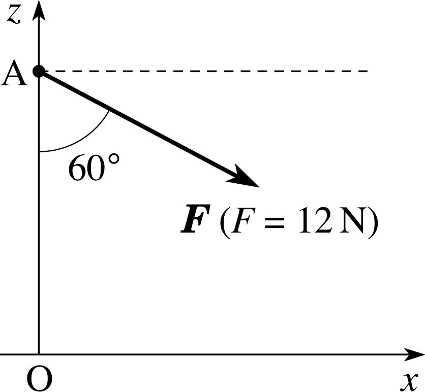
Figure 1 See Question R2.
Question R2
Find the components_of_a_vectorcomponents of the force F of magnitude_of_a_vector_or_vector_quantitymagnitude 12 N along both the x- and z–axes in Figure 1. If this force F were applied to a mass of 3.0 kg, placed at A, write down the x- and z–components of the acceleration of the mass.
Answer R2
The components_of_a_vectorcomponent of a force along a given direction is given by the product of the magnitude_of_a_vector_or_vector_quantitymagnitude of the force and the cosine of the angle between the force and the direction concerned. From Figure 1, the force is at an angle of 30° to the positive x–direction and 60° to the negative z–direction.
The x–component of F is
Fx = F cos 30° = (12 N) cos 30° = 10.4 N
The z–component of F is
Fz = −(12 N) cos 60° = −6.0 N
Newton’s second law of motion, F = ma, leads to
ax = Fx /m = 10.4 N/3.0 kg = 3.5 m s−2
az = Fz /m = 6.0 N/3.0 kg = 2.0 m s−2
Consult the relevant terms in the Glossary for further information.
Question R3
A mains water pipe section is of length 24 m, outer diameter 0.80 m, inner diameter 0.74 m and density 2.4 × 10³ kg m−3. Calculate its mass and the magnitude of its weight (taking the magnitude of the acceleration due to gravity to be 10 m s−2).
Answer R3
We solve this problem by subtracting a smaller solid cylinder with the inner radius from a larger solid cylinder with the outer radius.
Since mass = density × volume, it is necessary first to calculate the volumes of these solids. Do not forget to divide the diameter by two in order to calculate the radius.
The volume of a cylinder = cross–sectional area × height = πr2h
The volume of the larger cylinder is, therefore, π (0.40 m)2 × 24 m
The volume of the smaller cylinder is π (0.37 m)2 × 24 m
The mass of the hollow pipe is, therefore,
density × volume = 2.4 × 10³ kg m−3 × π × (0.402 − 0.372) m2 × 24 m = 4.2 × 10³ kg
and the magnitude of its weight is 4.2 × 10⁴ N.
Consult the relevant terms in the Glossary for further information.
2 Uniform circular motion
2.1 Basic definitions
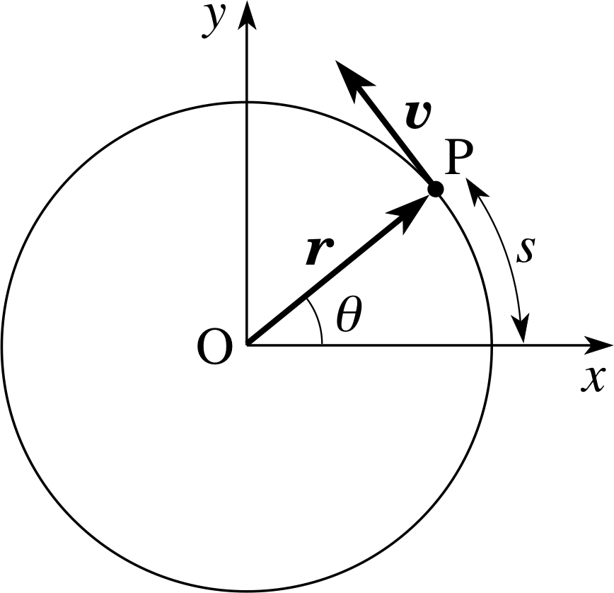
Figure 2 A particle undergoing uniform circular motion. The z–axis points out of the page, towards you.
When an object rotates steadily about a fixed axis, each of its constituent particles undergoes uniform circular motion. We therefore begin with a review of uniform circular motion, such as that shown in Figure 2. A mass m moves with constant speed υ around a circular path of radius r, in the (x, y) plane. The period of the motion is T and the frequency of the motion is f = 1/T. The particle traces out the circumference of the circle in time T so we have the relationship
υ = 2πr/T
At a certain time t, the particle is at point P, described by the position vector r. The particle’s position can also be represented by the angle θ relative to the x–axis or by the arc length s travelled round the circle from the x–axis. The angular speed is defined as ω = | dθ/dt | and remains constant because we are dealing with uniform circular motion. The particle makes one revolution, corresponding to ∆θ = 2π rad, in a time ∆t = T = 1/f, so we can also write
ω = π/T = πf
Substituting in our expression for the speed then gives υ = rω, a result which can also be confirmed by calculating the rate of change of the arc length:
$\upsilon = \left\lvert\,\dfrac{ds}{dt}\,\right\rvert = \left\lvert\,\dfrac{d(r\theta)}{dt}\,\right\rvert = \left\lvert\,r\dfrac{d\theta}{dt}\,\right\rvert = r\omega$(1)
The velocity of the particle is completely described by the velocity vector υ which has magnitude υ and is tangential to the circle.
Uniform circular motion is accompanied by centripetal acceleration, of magnitude a = υ2/r = rω2. This acceleration is always directed towards the centre of the circle so we can write the vector equation
a = −ω2r(2)
Newton’s second law of motion, F = ma, requires there to be a centripetal force of magnitude F = mυ2/r = mrω2, which is again directed towards the centre of the circle. This too can be written as a vector equation
F = −mω2r
making it clear that F and r are in opposite directions; both are perpendicular to the velocity vector υ which is tangential to the circle.
2.2 Constants of the motion
In the discussion above we have listed several quantities, some of which are scalar quantities and others of which are vector quantities.
✦ Of the quantities mentioned above, identify all the scalar quantities.
✧ The notation used in FLAP automatically identifies these for you: scalars are always denoted by non-bold italic symbols. So, the scalar quantities are: m, r, t, θ, s, υ, ω, T, f, a and F.
✦ Which of these quantities remain constant during uniform circular motion?
✧ From the full list we strike out all the quantities whose values vary (i.e. the variables t, θ and s); the remaining quantities m, r, υ, ω, T, f, a and F are constants of the motion (as it is uniform circular motion).
✦ Now identify all the vector quantities mentioned in the description of uniform circular motion given above.
✧ Again, the notation used in FLAP identifies these for you; vector quantities are always denoted by bold italic symbols. So, the vector quantities are: r, υ, a and F.
Question T1
Which of these vector quantities remain constant during the motion?
Answer T1
None of the vectors r, υ, a and F stay constant during the motion. Although their magnitudes stay constant, their directions change, rotating with the motion of the particle.
Question T2
Consider the force F acting on the particle over a short time interval ∆t.
(a) What is the work done ∆W by this force?
(b) What is the change in the particle’s kinetic energy in the time interval ∆t?
Answer T2
(a) The work done by the force F in a time ∆t, over which the position vector changes by ∆r = r2 – r1 is given by F∆r cos θ, where θ is the angle between the vectors F and ∆r. (This is referred to as the scalar product of the two vectors, F and ∆r, and is written as ∆W = F ⋅ ∆r.) In our case the tangential direction of ∆r is perpendicular to the radial direction of F so θ = 90° and cos θ = 0. The centripetal force therefore does no work on the particle.
(b) The change in the kinetic energy is equal to the work done and so is also equal to 0. Hence the kinetic energy of the particle is another scalar constant of the motion.
In summary, uniform circular motion is motion at constant speed along a circular path. The plane containing the path of the particle is called the plane of rotation. There are many scalar quantities which are constants of this motion. However, we have so far failed to find a single vector quantity which is a constant of this uniform circular motion. We shall now redress this shortcoming by defining a suitable angular velocity vector which does remain constant throughout the motion.
2.3 The angular velocity vector
Study comment If you have met the concept of angular velocity before you may skim through, or skip, this subsection.
For a particle in uniform circular motion we wish to introduce a constant vector quantity, the angular velocity ω, such that its constant magnitude is the angular speed ω = υ/r and its direction is also constant.
✦ What direction can reasonably be chosen for ω which remains fixed during the rotation?
✧ The direction of ω is taken to be along the axis of rotation, which is a line drawn perpendicular to the plane of rotation and passing through the centre of the circular path. This line is special because it remains perpendicular to each of r and υ, whatever their positions in the plane of rotation. If ω were to have a different orientation it would have a component in the plane of rotation and it would be very difficult to justify this component staying fixed, whilst r and υ rotate.
Figure 2 A particle undergoing uniform circular motion. The z–axis points out of the page, towards you.
The direction of the angular velocity vector is still not completely specified. The axis of rotation defines a single line, but is associated with two directions pointing in opposite senses along the line. To define the angular velocity vector it is necessary to choose one of these directions. The choice is made according to a standard convention, known as the right–hand grip rule; if the fingers of your right hand are curled around in the sense of rotation, then your extended thumb points along ω. This direction is out of the plane of the diagram in Figure 2 (i.e. along the positive z–axis).
To summarize:
The angular velocity vector ω has a magnitude equal to the angular speed ω. The direction of the angular velocity vector, ω is along the axis of rotation and is therefore perpendicular to plane of rotation and to the vectors r and υ. It points along the axis of rotation in a sense determined by the right–hand grip rule.
Angular velocity is a vector in the full sense of the word. It turns out, for example, that if a spinning object is placed on a rotating platform (say, the second hand of a watch on the arm of a child standing on a rotating roundabout) the net effect of these two rotations is given by the vector sum of the two angular velocity vectors. The vector nature of angular velocity is reflected in our notation: like any other vector, it is represented by a directed line segment – that is by a straight line with an arrow. The length of the arrow is proportional to the angular speed ω and the direction of the arrow is the direction of ω. The sum of two angular velocity vectors can then be carried out algebraically (by adding components) or geometrically (by the triangle rule).
Aside It is tempting to represent angular velocity by a curved line with an arrow indicating the sense of rotation, and to use descriptive words, such as clockwise and anticlockwise, which carry this message. Such a representation is best avoided because it does not adequately reflect the vector nature of angular velocity and is of no help when adding two angular velocities together. i
We have arrived at a sensible definition for the angular velocity vector in the special case of a particle undergoing the uniform circular motion. It is natural to ask whether this concept can be profitably extended to other types of rotation – for example, to the elliptical orbit of a planet around the Sun. Such extensions can certainly be made but a completely general definition of angular velocity is complicated and is rarely found in textbooks. You might think this to be a curious omission, but it actually is rather revealing: it betrays the fact that angular velocity is of kinematic, rather than dynamic interest – that is, it is rarely used in equations of motion involving external influences, such as forces.
In Section 4 we will introduce a new vector quantity, the angular momentum, which plays a central role in rotational dynamics: the rate of change of angular momentum is directly determined by the external influences that are acting. Angular velocity is most useful when it is simply related to the angular momentum. However when the relationship between angular velocity and angular momentum is complicated (as is the case for planetary orbits) this may simply indicate that angular velocity does not provide a very convenient description of the motion.
This discussion of the central importance of angular momentum and the more subsidiary role of angular velocity is, of course premature, but it gives you some early insight of the central message of this module and provides a signpost to future sections. In particular, the definition of angular momentum can be identified as an urgent objective. This will be reached in Section 4, but first it is necessary to review some background material on vectors. The two concepts we need to cover are those of unit vectors and vector products.
3 Unit vectors and vector products
Study comment If you are familiar with the representation of vectors in terms of unit vectors and with the idea of a vector product you will find this section contains much revision material and you may only need to glance at it. If you have not met these concepts before you may find this section rather formal: if so, be prepared to read it briskly and to return to it later, when you are in a position to appreciate how these mathematical ideas are used in the theory of rotation.
3.1 Unit vectors
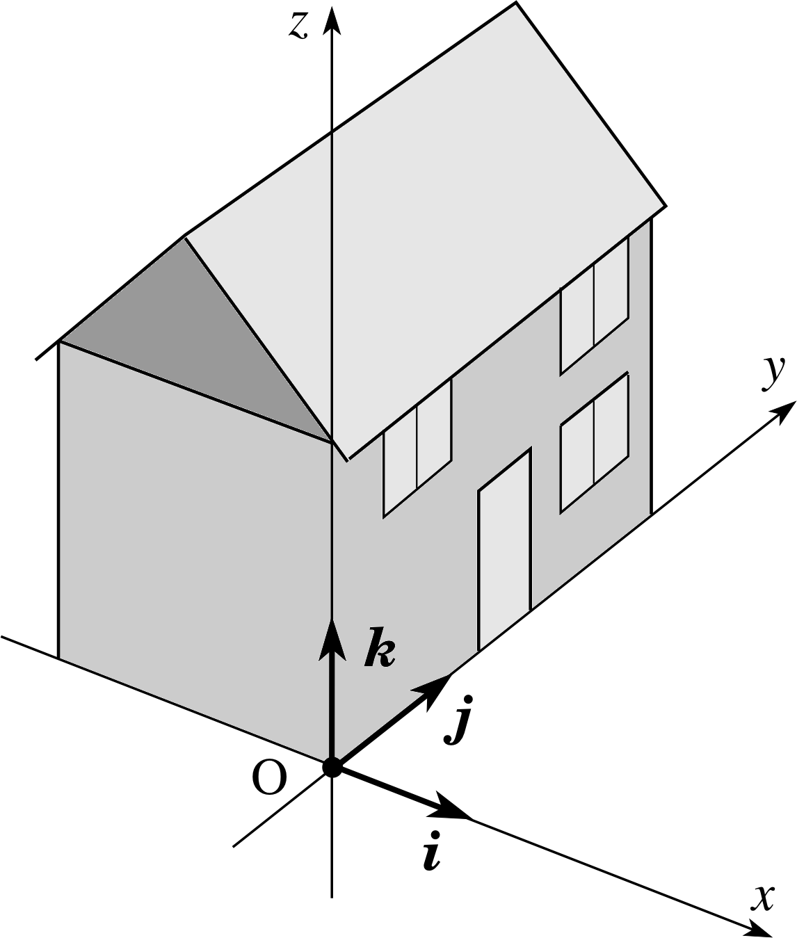
Figure 3 Fixed unit vectors in a right–handed coordinate system. (A coordinate system is said to be right-handed if a corkscrew rotated from the x–axis towards the y–axis advances in the direction of the z–axis.) The unit vectors i, j, and k provide directional information only.
A unit vector is a vector of unit magnitude: its magnitude is not equal to 1 metre, but to the pure number 1, which has no units. This is rather an abstract idea, but it allows us to represent many other vectors in terms of unit vectors. For example, suppose that the unit vector i points along the x–direction. Then the vector (5 m) i represents a displacement of length 5 m in the x-direction and the vector (5 m s−1) i represents a velocity with magnitude (speed) 5 m s−1 in the x–direction. The unit vector i indicates direction, but contains no information about magnitude or units.
It is useful to define three unit vectors, i, j and k, which point, respectively, along the x–, y– and z–axes of a right–handed coordinate system (Figure 3). Then any position vector r = (x, y, z) can be expressed as a vector sum of x i, y j and z k:
r = x i + y j + z k
Any other vector, such as a force vector, F = (Fx, Fy, Fz) can be represented in a similar way:
F = Fx i + Fy j + Fz k
Quantities like Fx i are called component vectors. These are genuine vectors with magnitude and direction and should not be confused with scalar quantities such as Fx, which are called components.
Question T3
Suppose that the particle in Figure 2 moves at 10 m s−1 in the (x, y) plane, along a circular path of radius 2 m, and that its angular position is θ = 40°. Express (a) the position vector of the particle and (b) the velocity of the particle in terms of unit vectors along the x–, y– and z–axes.
Answer T3
The (x, y)-coordinates of P are (2 cos 40°, 2 cos 50°) m and the (x, y)-components of its velocity are (υx, υy) = (−10 cos 50°, 10 cos 40°) m s−1. The z–component of position and velocity are zero. So the required position and velocity vectors are
r = x i + y j = (2 cos 40° i + 2 cos 50° j) m = (1.53 i + 1.29 j) m
υ = υx i + υy j = (−1 cos 50° i + 1 cos 40° j) m s−1 = (−6.43 i + 7.66 j) m s−1
Question T4
A particle moves at constant angular speed ω in a circle of radius r in the (x, y) plane. The position vector describing this uniform circular motion is r = r [icos(ωt) + j sin(ωt)]. Confirm Equation 2,
a = −ω2r(Eqn 2)
by differentiating this vector twice.
Answer T4
The differentiation can be carried out using the normal rules of calculus and remembering that the vectors i and j are constant. Thus
$\upsilon = \dfrac{d\boldsymbol{r}}{dt} = \dfrac{d}{dt}r[\boldsymbol{i}\cos(\omega t)+\boldsymbol{j}\sin(\omega t)] = r\omega[-\boldsymbol{i}\sin(\omega t)-\boldsymbol{j}\cos(\omega t)]$
and
$\boldsymbol{a} = \dfrac{d\boldsymbol{\upsilon}}{dt} = \dfrac{d}{dt}r\omega[-\boldsymbol{i}\sin(\omega t)+\boldsymbol{j}\cos(\omega t)] = r\omega^2[-\boldsymbol{i}\cos(\omega t)-\boldsymbol{j}\sin(\omega t)] = -\omega^2\boldsymbol{r}$
as required.
3.2 Vector products
Figure 2 A particle undergoing uniform circular motion. The z–axis points out of the page, towards you.
The second concept we need is that of a vector product (sometimes called the cross product) of two vectors. i
Vector products
Given any two vectors, a and b, which are inclined at an angle θ to one another, their vector product is written as a × b and has the following properties:
- it is a vector;
- it has magnitude ab sin θ; i
- its direction is perpendicular to both a and b and is defined equivalently either by a corkscrew rule (Figure 4a) or by the right–hand rule (Figure 4b).
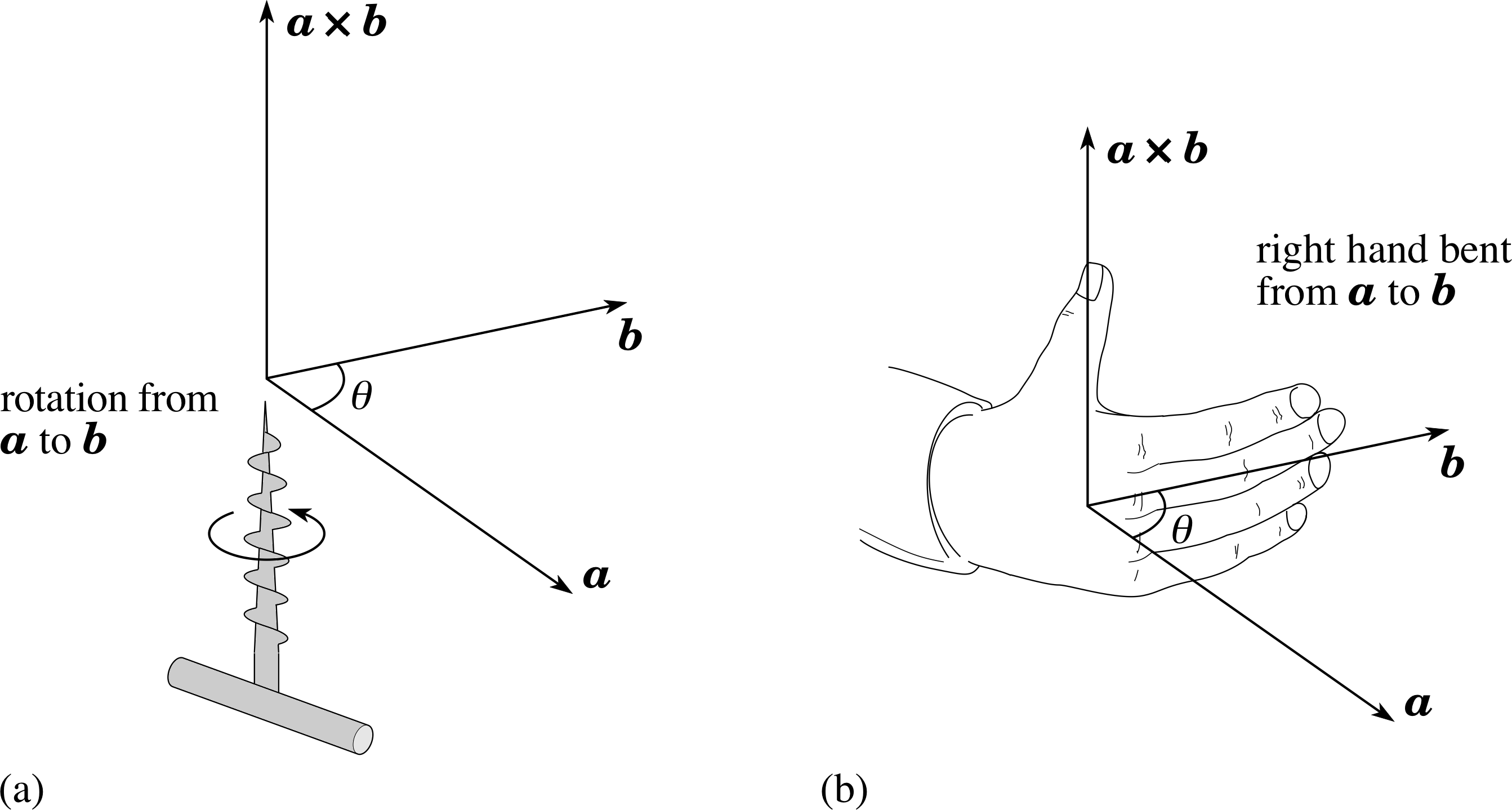
Figure 4 Defining the direction of the vector product a × b of two vectors a and b according to the corkscrew rule and the right–hand rule. (a) The corkscrew rule: when a corkscrew is turned from a to b through the angle θ, the tip of the corkscrew advances in the direction of a × b. (b) The right–hand rule: when the fingers of the right hand are curled in the direction from a to b then the thumb points in the direction of a × b (rather than in the opposite direction).
Figure 3 Fixed unit vectors in a right–handed coordinate system. (A coordinate system is said to be right-handed if a corkscrew rotated from the x–axis towards the y–axis advances in the direction of the z–axis). The unit vectors i, j, and k provide directional information only.
Some properties of the vector product follow immediately from its definition.
- 1
-
The order of the vectors in a vector product is important. If the order of the two vectors is reversed then the sign of the vector product is reversed
b × a = −a × b(3)
- 2
-
Because sin 0° = sin 180° = 0, the vector product of any two parallel (or antiparallel) vectors is zero. Thus, for any scalar quantity λ and any vector a we have
a × (λa) = 0(4)
and, in particular, the vector product of any vector with itself is zero:
a × a = 0
- 3
-
Using the right–hand rule and adopting a right–handed coordinate system as in Figure 3, we can easily calculate the vector products of our unit vectors:
i × i = 0 j × j = 0 k × k = 0
i × j = k k × i = j j × k = i(5)
j × i = − k i × k = − j k × j = −i
These identities help us to calculate the components of a vector product. If we are given two vectors
a = ax i + ay j + az k
b = bx i + by j + bz k
their vector product is given by
a × b = (ax i + ay j + az k) × (bx i + by j + bz k)
a × b = axby(i × j) + axbz(i × k) + aybx (j × i) + aybz (j × k) + azbx(k × i) + azby(k × j) i
So, using the known vector products of the unit vectors we obtain
a × b = (aybz − azby) i + (azbx − axbz) j + (axby − aybx) k(6)
This formula can be regarded as an alternative definition of the vector product of two vectors, based on algebra rather than geometry. The geometric definition given in the box earlier is more immediately appealing but the algebraic definition is sometimes easier to implement, especially when writing computer programs.
- 4
-
We often need the vector product of two vectors a and b that depend on time; the rate of change of the vector product a × b is then given by the usual product rule of differentiation:
$\dfrac{d}{dt}(\boldsymbol{a \times b}) = \left(\boldsymbol{a\times}\dfrac{d\boldsymbol{b}}{dt}\right) + \left(\dfrac{d\boldsymbol{a}}{dt}\boldsymbol{\times b}\right)$(7) i
where, in view of Equation 3,
b × a = −a × b(Eqn 3)
care must be taken to preserve the order of the vectors (a preceding b throughout).
Question T5
In a triangle PQR the displacement vector from P to Q is a and the displacement vector from P to R is b. What is the geometric significance, if any, of the quantity ½ | a × b |?
Answer T5
Let θ be the angle between a and b. Then, by definition,
½ | a × b | = ½ ab sin θ = ½ a × (b sin θ)
This can be interpreted as half the base times the height of the triangle, which is an expression for its area.
Question T6
A particle travels at constant velocity υ along a straight line. An origin of coordinates O is chosen that lies a distance b away from this straight line. i The position vector of the particle relative to O is r. Show that the vector product r× υ is independent of time.
[Hint: As a first step, split r into two perpendicular vectors.]
Answer T6
The position vector r of the particle can be decomposed into a (perpendicular) displacement r⊥from the origin O to the nearest point on the straight line and a (parallel) displacement r|| along the straight line: r = r⊥ + r||. Then,
r × υ = (r⊥ × υ) + ( r|| × υ)
Because r|| is parallel to υ, the second vector product is zero and we are left with r⊥ × υ). This is a constant vector (because r⊥ and υ are both constant vectors). It has a constant direction (perpendicular to the plane containing O and the straight line) and a constant magnitude equal to bυ (because r⊥ has length b and is perpendicular to υ).
4 Rotational dynamics and angular momentum
When an extended object is subjected to an external force several things may happen. The object may:
- 1
-
translate (i.e. move bodily) through space;
- 2
-
rotate about an axis of fixed or varying orientation;
- 3
-
distort in shape, as in a vibration.
In general, these different types of motion will all take place together and it may not be easy to unravel them. We shall simplify matters by concentrating on single particles and rigid bodies – that is, bodies that cannot be distorted. The motion of a rigid body can always be regarded as a combination of a translation and a rotation.
4.1 Centre of mass and translational motion
The distinction between translation and rotation is not entirely trivial. If you think of a spanner being thrown so that it spins end-over-end, it is clear that each end of the spanner will both translate and rotate. Nevertheless, there is one special point in the spanner which does not rotate, but which follows the parabolic path expected for a projectile: this special point is called the centre of mass of the spanner. In general, any object has a special point, called its centre of mass, whose rate of acceleration is determined by the total mass of the object and the total external force acting on it, according to Newton’s second law of motion. The centre of mass of an extended object can therefore be treated exactly like the idealized point particle encountered in elementary formulations of Newtonian mechanics.
The centre of mass of an object can be characterized in a second way. In general, when a single force is applied to an initially stationary body it causes translation of the centre of mass and rotation of the rest of the body around the centre of mass. However, if the force acts along a line that passes through the centre of mass, no rotational motion is generated: the body simply accelerates through space without changing its orientation. The centre of mass is the only point that has this property.
One further property of the centre of mass is useful in many problems. When a rigid body is placed in a uniform gravitational field, such as that found near the Earth’s surface, the gravitational force acting on the body has exactly the same effect as if it were a single force applied at the body’s centre of mass. By itself, gravity near the Earth’s surface is therefore incapable of generating rotational motion: if you observe rotation developing when an object is dropped, this must be due to other influences such as air resistance.
The centre of mass provides us with a convenient way of distinguishing between translation and rotation. Motion of the centre of mass through space tells us about translation of the body and rotation about an axis i through the centre of mass tells us about rotation of the body. Any motion of a rigid body can be regarded as a combination of a translation of the centre of mass and a rotation about the centre of mass.
The translational motion of a single particle is conveniently analysed in terms of its linear momentum (usually simply called momentum). For a single particle of mass m moving with velocity υ, the momentum p is defined as:
For a particle p = mυ(8a)
Momentum is an important property for two main reasons:
- 1
-
Newton’s second law of motion can be expressed in terms of momentum:
For a particle F = dp/dt(9a)
- 2
-
When the resultant external force F is zero, the rate of change of momentum is zero so p is a constant vector – the particle’s momentum is conserved.
The fact that the centre of mass behaves as an idealized particle allows us to apply these ideas to an extended body. If the object is regarded as a collection of N particles, its total momentum P is defined by adding together the momenta of its constituent particles:
$\displaystyle \boldsymbol{P} = \sum_{i=1}^N \boldsymbol{P}_i$
For an object of mass M, whose centre of mass moves at velocity υcm, this momentum is also given by
For an extended object P = Mυcm(8b)
and, if the body experiences a resultant external force F, Newton’s second law gives
For an extended object F = dP/dt(9b)
When the resultant external force is zero, the rate of change of momentum is zero so P is a constant vector – the object’s momentum is conserved.
We would like to establish analogous results for rotational motion. To do this we need to introduce two new concepts, angular momentum and torque, which are the rotational analogues of (linear) momentum and force.
4.2 Introducing angular momentum
We begin with a general definition of the angular momentum of a particle. Suppose that the particle has position vector r (relative to a chosen origin O) and momentum p. Then
the angular momentum of the particle about the chosen origin O is defined as the vector product:
L = r × p(10) i
This vector quantity has magnitude L = rp sin θ = mυr sin θ
where θ is the angle between the directions of r and p. Its direction is perpendicular to both r and p, in a sense determined by the right–hand rule.
The components of the angular momentum vector follow immediately from its definition and from Equation 6,
a × b = (aybz − azby) i + (azbx − axbz) j + (axby − aybx) k(Eqn 6)
which gives
L = a × b = (ypz − z py) i + (z px − x pz) j + (x py − ypx) k
In order to see what this definition means in physical terms it is best to consider some examples. We begin with the simple case of a particle undergoing uniform circular motion at constant angular velocity ω in the (x, y) plane with the origin O at the centre of the circle (Figure 5). This is the rotational equivalent of uniform linear motion at constant velocity υ.
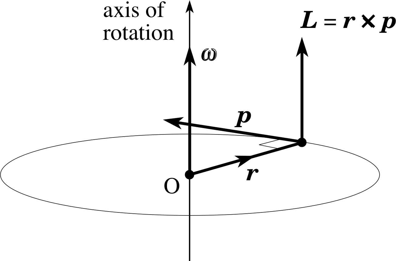
Figure 5 A particle of mass m undergoes uniform circular motion in the (x, y) plane. Relative to an origin O at the centre of the circle the particle has position vector r and its momentum is p.
We note that:
- 1
-
Because L = a × b is perpendicular to both r and p, it must point along the axis of rotation. Moreover, application of the right–hand rule shows that L points in the same direction as ω.
- 2
-
Because the angle between r and p is 90°, the magnitude of the angular momentum vector is L = rp = mυr. Using Equation 1,
$\upsilon = \left\lvert\,\dfrac{ds}{dt}\,\right\rvert = \left\lvert\, \dfrac{d(r\theta)}{dt}\,\right\rvert = \left\lvert\,r\dfrac{d\theta}{dt}\,\right\rvert = r\omega$(Eqn 1)
this becomes
L = mr2ω
So the angular momentum is proportional to the angular speed. Since L and ω have been shown to point in the same direction this result can be expressed in vector form:
L = mr2ω = Iω(11a)
where the constant of proportionality I = mr2 is called the moment of inertia of the orbiting particle.
Because the scalars m, r and ω are all constant, we see that the angular momentum vector is constant in magnitude, as well as being constant in direction. We therefore conclude that the angular momentum vector of the particle in Figure 5 is constant: like angular velocity the angular momentum L is a vector constant of the motion.
These relationships form the basis of an analogy between uniform linear motion and uniform circular motion. Table 1 shows the details.
| Uniform linear motion | Uniform circular motion |
|---|---|
| position coordinate x | angular position coordinate θ |
| speed υ = | dx/dt | | angular speed ω = | dθ/dt | |
| velocity υ = dr/dt | angular velocity ω |
| mass m | moment of inertia I = m r2 |
| momentum p = mυ (a vector constant of the motion) |
angular momentum L = r × p = Iω (a vector constant of the motion) |
For example, corresponding to mass (which measures the translational inertia of a particle in linear motion) we have the moment of inertia I = mr2 (which measures the rotational inertia of a particle in circular motion) and corresponding to momentum p we have angular momentum L.
The analogy outlined in Table 1 masks one important difference: the angular momentum vector L depends on the choice of origin of the coordinate system while the linear momentum vector p does not.
To illustrate this point, consider the same motion as in Figure 5, but suppose that the origin is at the point O in Figure 6, on the axis of rotation but not in the plane of rotation. The position vector of the particle can then be represented as the vector sum of r|| which is parallel to the axis of rotation and r⊥ which is perpendicular to the axis of rotation.
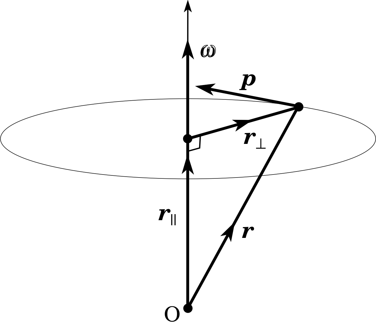
Figure 6 The same motion as in Figure 5 but analysed using an origin O which is on the axis of rotation, but not in the plane of rotation. Relative to this new origin the position vector of the particle is r = r|| + r⊥ where r|| is a component vector along the axis of rotation and r⊥ is a component vector perpendicular to the axis of rotation.
Thus,
L = r × p = (r|| + r⊥) × p = (r|| × p) + (r⊥ × p)(12)
The second vector product on the right–hand side of Equation 12 is clearly the same as the angular momentum calculated for the situation in Figure 5. Since this contribution to the angular momentum is parallel to the axis of rotation we denote it by L|| and write
L|| = r⊥ × p = mr⊥2ω(11b)
There remains the first vector product on the right–hand side of Equation 12. This vector product is perpendicular to the axis of rotation, directed radially inwards along −r⊥, and is therefore denoted by L⊥. It is certainly not zero and does not remain constant, but swings around in the plane of rotation at the same rate as the orbiting particle. Thus, adding the two contributions L|| and L⊥ together leads to a more complicated description than before, one in which L is no longer parallel to ω, and the simple analogy outlined in Table 1 is destroyed.
You might suppose that the chameleon–like nature of the angular momentum vector (depending on the choice of origin of coordinate system) would undermine its use in descriptions of rotational motion. Figures 5 and 6 correspond to alternative outlooks on the same motion, so it might seem unreasonable for the angular momentum vector to have very different properties in these two cases. Surprisingly, this is not so. The next section will show why angular momentum plays a central role in rotational motion and why the differences that arise from different choices of origin turn out to be unimportant after all.
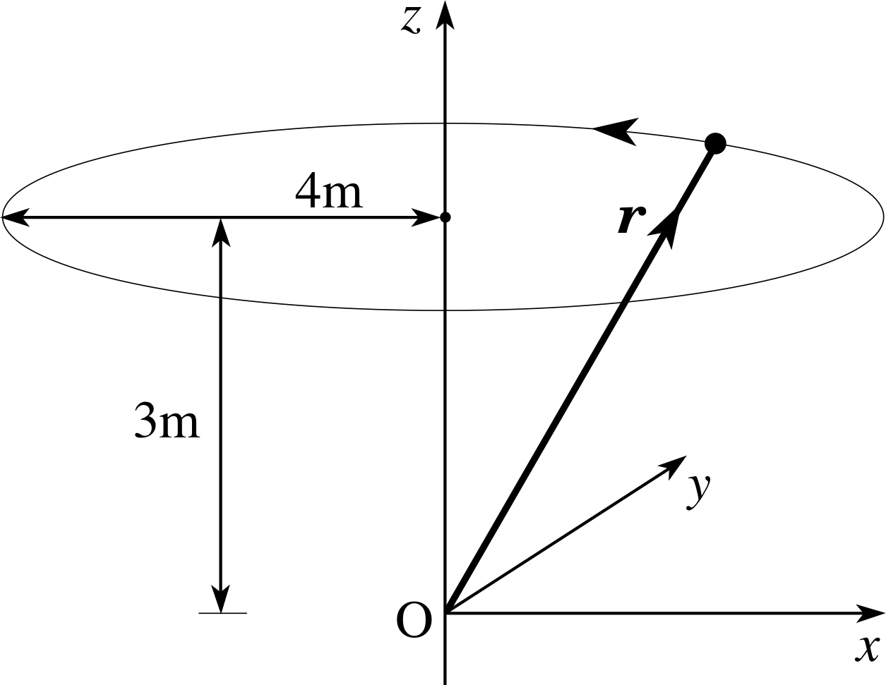
Figure 7 See Question T7.
Question T7
A particle of mass 5 kg is in uniform circular motion in the (x, y) plane with speed 10 m s−1 on a path of radius 4 m. The motion is analysed using an origin on the axis of rotation but displaced 3 m from the plane of rotation (Figure 7). Calculate (a) the magnitude of the angular momentum about O, (b) the z–component of the angular momentum about O, (c) the maximum value of the x–component of the angular momentum, Lx, and (d) the minimum value of Lx.
Answer T7
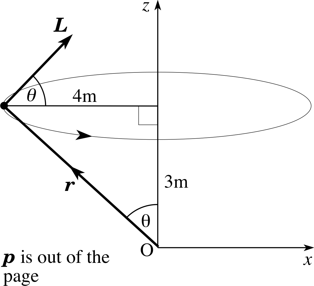
Figure 17 See Answer T7.
(a) The angular momentum vector is given by the vector product
L = r⊥ × p = r × mυ
The vectors r and p are perpendicular (in spite of the fact that O does not lie in the plane of the orbit) so the magnitude of L is given by
$\lvert\,\boldsymbol{L}\,\rvert = \rm \sqrt{\smash[b]{(3\,{\rm m})^2+(4\,{\rm m})^2}} \times(5\,kg\times10\,m\,s^{-1})\times \sin90° = 250\,kg\,m\,s^{-1}$
(b) L is perpendicular to r and p and, for the sense of rotation shown in Figure 17, has a positive z–component (by the right–hand rule). In Figure 17, the vector r makes an angle θ with the z–axis, so the vector L makes an angle (90 − θ)° with the z–axis. Thus
$L_z = \lvert\,\boldsymbol{L}\,\rvert\cos(90°-\theta) = \lvert\,\boldsymbol{L}\,\rvert\sin\theta\\\phantom{L_z} = \rm 250\,kg\,m\,s^{-1}\times\dfrac{4\,m}{\sqrt{\smash[b]{(3\,m)^2+(4\,m)^2}}}\,m = 200\,kg\,m\,s^{-1}$
(c) The maximum value of Lx occurs at the point shown in Figure 17. In terms of the angle θ,
(Lx)max = | L | cos θ = 250 kg m s−1 × $\frac{3}{5}$ =150 kg m s−1
(d) Similarly, the minimum value of Lx occurs when the particle is at the opposite point on the circle to that shown in Figure 17, and
(Lx)min = −150 kg m s−1
4.3 Rate of change of angular momentum and torque
For both single particles and extended bodies you have seen that the rate of change of linear momentum is determined by the total external force (Equations 9a and 9b).
For a particle F = dp/dt(Eqn 9a)
For an extended object F = dP/dt(Eqn 9b)
The great importance of angular momentum stems from the fact that it obeys a similar law: the rate of change of angular momentum is determined by the external forces on the system.
To establish this fact we differentiate both sides of Equation 10,
L = r × p(Eqn 10)
with respect to time, using Equation 7,
$\dfrac{d}{dt}(\boldsymbol{a \times b}) = \left(\boldsymbol{a\times}\dfrac{d\boldsymbol{b}}{dt}\right) + \left(\dfrac{d\boldsymbol{a}}{dt}\boldsymbol{\times b}\right)$(Eqn 7)
to help us differentiate the vector product. This gives
$\dfrac{d\boldsymbol{L}}{dt} = \dfrac{d}{dt}(\boldsymbol{r \times p}) = \left(\boldsymbol{r\times}\dfrac{d\boldsymbol{p}}{dt}\right) + \left(\dfrac{d\boldsymbol{r}}{dt}\boldsymbol{\times p}\right)$ i
By Newton’s second law, dp/dt = F and from the definitions of velocity and momentum dr/dt = υ and p = mυ. Substituting these results in the above equation gives
$\dfrac{d\boldsymbol{L}}{dt} = (\boldsymbol{r\times F}) + (\boldsymbol{\upsilon\times}m\boldsymbol{\upsilon})$
Because υ is parallel to mυ, the second term on the right–hand side vanishes (see Equation 4)
a × (λa) = 0(Eqn 4)
and we are left with
$\dfrac{d\boldsymbol{L}}{dt} = (\boldsymbol{r\times F})$
The vector quantity (r × F) which appears on the right–hand side of this equation is called the torque and is denoted by the symbol Γ. i
Thus
torque Γ = r × F(13) i
and
for a single particle $\dfrac{d\boldsymbol{L}}{dt}$ = Γ(14a)
The torque vector is a measure of the turning influence experienced by the particle and Equation 14a can be regarded as the rotational analogue of Newton’s second law, dp/dt = F. Just as changes in (linear) momentum are caused by forces, so changes in angular momentum are caused by torques.
Equation 14a has been derived for a single particle but a very similar result applies to an extended object.
If the object is regarded as a collection of N particles, its total angular momentum L is defined by adding together the angular momenta of its constituent particles:
$\displaystyle \boldsymbol{L} = \sum_{i=1}^N \boldsymbol{L}_i$
Then the rate of change of the total angular momentum is given by
for an object $\dfrac{d\boldsymbol{L}}{dt}$ = Γ(14b)
where Γ is now the total external torque (given by the vector sum of all the external torques that are applied to the object).i Note that only external torques need be considered here, in spite of the fact that internal torques are also present. An extended object can be regarded as a collection of many different particles which exert forces on one another and these forces produce torques. However, the important point is that these internal torques cancel out and do not affect the total angular momentum. (A rigid body cannot start to rotate unless torques are applied to it from the outside.)
Question T8
State in words, as fully and concisely as you can, the physical content of Equation 14b.
for an object $\dfrac{d\boldsymbol{L}}{dt}$ = Γ(Eqn 14b)
Answer T8
When a resultant external torque acts on the body its angular momentum changes. The rate of change of the angular momentum vector is equal in magnitude and direction to the resultant external torque vector. Notice how many words are needed to convey the same information as is given by the vector equation, Equation 14b!
for an object $\dfrac{d\boldsymbol{L}}{dt}$ = Γ(Eqn 14b)
Equations 14a and14b are the most important results of this module. They are the analogues of Equations 9a and 9b for linear motion
For a particle F = dp/dt(Eqn 9a)
For an extended object F = dP/dt(Eqn 9b)
and reveal the central role played by angular momentum and torque in discussions of rotational motion. Angular momentum has already been discussed at some length but the concept of torque needs further explanation.
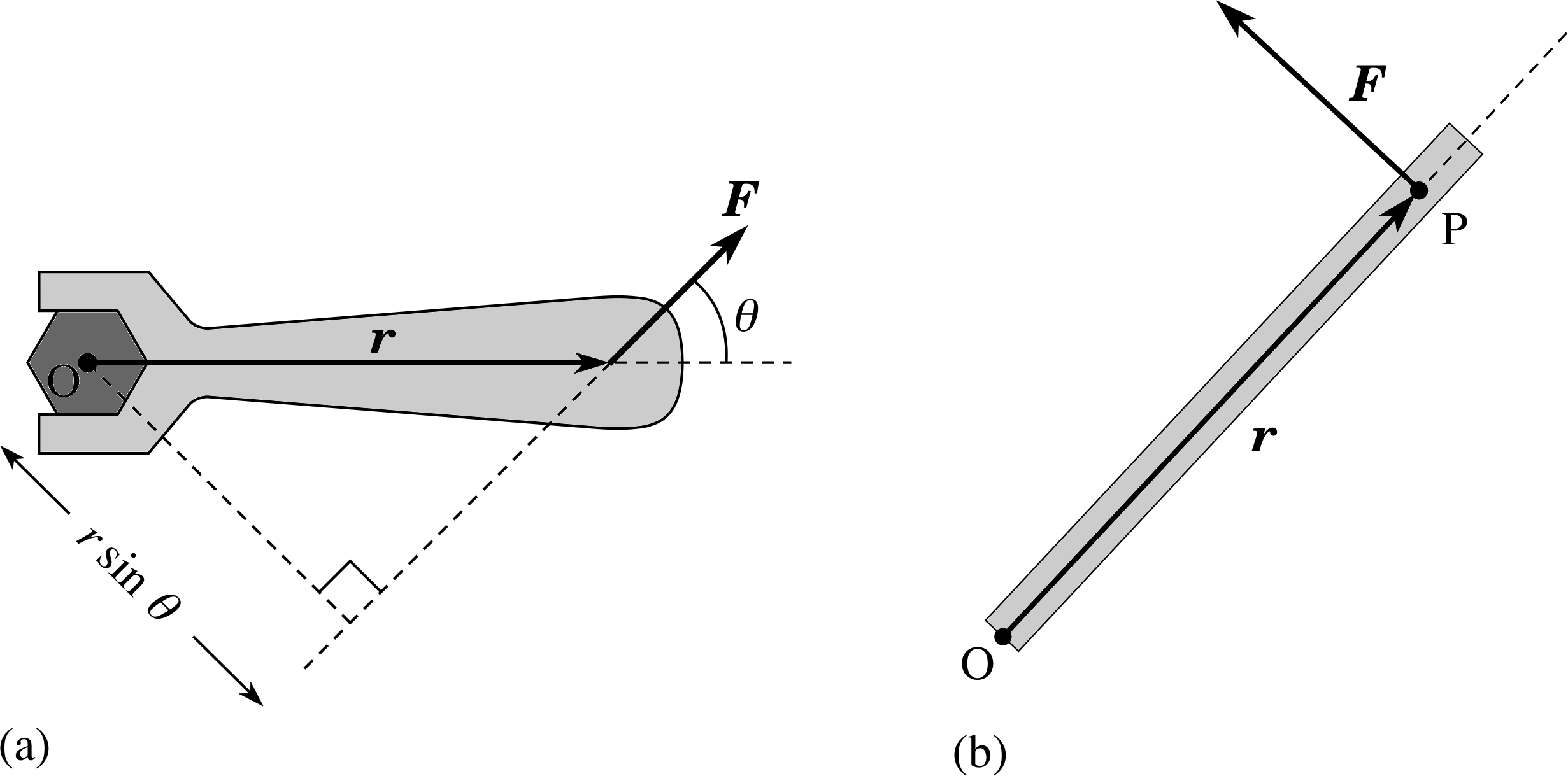
Figure 8 (a) The turning effect or torque produced by a force F applied at position r from an origin O. The plane containing the vectors r and F is shown and θ is the smaller angle between these two vectors. (b) Closing a heavy door with the optimum position and angle of an applied force. The torque Γ acts up the axis of the hinge, towards you.
As an example, consider Figure 8a which shows a single force F which is applied to an extended object and whose point of application has position vector r relative to a chosen origin. The direction of the torque is perpendicular to both r and F and therefore points along the axis of the rotation that the force would promote if the object were pivoted about the origin. The magnitude of the torque is
Γ = rF sin θ(15)
where F is the magnitude of the force, r is the distance of the point of application of the force from the origin and θ is the smaller angle between the vectors r and F.
Figure 8a shows that the magnitude of the torque can also be interpreted as the product of the magnitude of the force and the perpendicular distance between its line of action and the origin.
Notice that the magnitude of the torque depends on three factors:
- 1
-
The magnitude F of the applied force;
- 2
-
The distance r from the chosen origin O to the point of O application of the force. (This distance is sometimes called the lever arm.)
- 3
-
The direction of the applied force. The greatest turning effect is experienced when r (a) and F are mutually perpendicular (θ = 90°) but no turning effect is felt if θ = 0° or θ = 180°(i.e. if the line of action of the applied force passes through the pivot).
These factors are in accord with common experience. For example, a heavy door is most easily closed if the force is applied as far as possible from the hinge and perpendicular to the face of the door, as in Figure 8b. By contrast, if the line of action of the force were to pass through the hinge then the door could not be closed, however large the force.
As in the case of angular momentum it is also possible to express the torque vector in component form.
Using Equation 6,
a × b = (aybz − azby) i + (azbx − axbz) j + (axby − aybx) k(Eqn 6)
we have
Γ = r × F = (yFz − zFy) i + (zFx − xFz) j + (xFy − yFx) k(16)
where r = (x, y, z) is the position vector of the point of application of the force F = (Fx, Fy, Fz).
Question T9
The hour hand on a clock has a uniform cross section, is of mass 3.6 kg and is 0.4 m long. Taking the origin to be the centre of the clock face, what is the torque about the central axis through the clockface due to the weight of the hand when the clock reads 4 o’clock? Answer this question using (a) Equation 15,
Γ = r F sin θ(Eqn 15)
and (b) Equation 16. [Hint: take g = 9.8 m s−2.]
Answer T9
(a) Each hour corresponds to 30° on the clock face so at 4 o’clock the hour hand makes an angle of 60° with the downward vertical. The hand is pivoted at the centre of the clock face O and the force of gravity acts downwards as if it were concentrated at the centre of mass of the hand, half–way along its length. The magnitude of the torque about the central axis through O is therefore
Γ = rF sin ϕ = 0.2 m × 3.6 kg × 9.8 m s−2 × sin 60° = 6.1 N m
The torque vector is at right–angles to the plane of the clock face and, by the right–hand rule, points into the clock face, as seen from the front.
(b) Choose a right–handed coordinate system with origin O at the centre of the clock face, x–axis pointing from O to 3 o’clock, y–axis pointing from O to 12 o’clock and z–axis pointing from O out of the clock face. The weight of the clock hand is then described by the vector
F = −mg j = −3.6 kg × 9.8 m s−2 j
with point of application
r = 0.2 m(cos 30° i + cos 60° j)
The torque vector about O is then given by
r × F = 0.2 m(cos 30° i + cos 60° j) × (−3.6 kg × 9.8 m s−2 j)
which reduces to
r × F = −0.2 m × 3.6 kg × 9.8 m s−2 cos 30° k = −(6. N m) k
as before.
One of the most fundamental and far–reaching consequences of Equations 14a and 14b
for a single particle $\dfrac{d\boldsymbol{L}}{dt}$ = Γ(Eqn 14a)
for an object $\dfrac{d\boldsymbol{L}}{dt}$ = Γ(Eqn 14b)
arises when the total external torque is zero. When this happens, dL/dt is zero so the angular momentum vector L remains constant.
The law of conservation of angular momentum states that when no resultant external torque acts on a body, its angular momentum stays constant.
Figure 5 A particle of mass m undergoes uniform circular motion in the (x, y) plane. Relative to an origin O at the centre of the circle the particle has position vector r and its momentum is p.
It is important to realize that the condition of no resultant torque does not imply the absence of a resultant force. Returning to the example of a particle in uniform circular motion (Figure 5) it is clear that a force is acting on the particle: this is the centripetal force needed to deflect the particle from straight–line motion and to hold it on a circular path.
(The centripetal force is an example of a central force – that is, a force whose line of action passes through a fixed point.) The centripetal force always points towards the centre of the circle so it produces no torque about an origin at the centre of the circle.
The law of conservation of angular momentum then guarantees that the angular momentum of the particle is constant (again referred to an origin at the centre of the circle). The angular momentum is constant in magnitude (mrω2 remains fixed) and constant in direction (the motion is confined to a single plane, the plane of rotation).
It is worth emphasizing that the above discussion relies on the origin being at the centre of the circle. In Figure 6 a different origin O has been chosen, on the axis of rotation but out of the plane of rotation. In this case you have already seen (Equation 12)
L = r × p = (r|| + r⊥) × p = (r|| × p) + (r⊥ × p)(Eqn 12)
that the angular momentum has a component L⊥ = r|| × p which is perpendicular to the axis of rotation and is not conserved. This is not a problem because, relative to the origin of Figure 6, the particle experiences a torque Γ⊥ = r|| × F where F is the centripetal force acting along −r⊥.
Figure 6 The same motion as in Figure 5 but analysed using an origin O which is on the axis of rotation, but not in the plane of rotation. Relative to this new origin the position vector of the particle is r = r|| + r⊥ where r|| is a component vector along the axis of rotation and r⊥ is a component vector perpendicular to the axis of rotation.
Moreover, because r|| is constant we have
$\dfrac{d\boldsymbol{L}_\perp}{dt} = \boldsymbol{r}_\Vert \boldsymbol{\times} \dfrac{d\boldsymbol{p}}{dt} = \boldsymbol{r}_\Vert \boldsymbol{\times}\boldsymbol{F}$ = Γ⊥
so the rate of change of L⊥ is explained by the existence of Γ⊥. At the same time, the component of angular momentum parallel to the axis of rotation remains constant because there is no torque in that direction.
Two morals may be drawn from this. First, Equations 14a and 14b
for a single particle $\dfrac{d\boldsymbol{L}}{dt}$ = Γ(Eqn 14a)
for an object $\dfrac{d\boldsymbol{L}}{dt}$ = Γ(Eqn 14b)
are valid no matter which fixed point is chosen as origin: this allays the fears expressed at the end of Subsection 4.1 because the chameleon–like nature of angular momentum is matched by that of the torque. Second, we note that an appropriate choice of origin can simplify the analysis. In the above example, it is sensible to choose the origin to be at the centre of the circle because this ensures a vanishing torque and allows the law of conservation of angular momentum to be used. Other choices are not wrong, but they lead to more work.
4.4 Uni–axial rotation
The simplest type of rotational motion that involves a non–zero torque occurs when the axis of rotation is fixed relative to the rotating body and maintains a fixed orientation. A good example is provided by an opening door, where the axis of rotation runs down one side of the door and maintains a vertical orientation. Such a motion is said to be a uni–axial rotation.
Uni-axial rotation is simple because the angular velocity vector points along the known, fixed axis. The angular momentum and torque vectors need not point along this axis (because they depend on the choice of origin) but we are really only interested in the components of these vectors along the axis. Isolating the component vectors in Equation 14b,
for an object $\dfrac{d\boldsymbol{L}}{dt}$ = Γ(Eqn 14b)
that point along the axis of rotation gives
$\dfrac{d\boldsymbol{L}_\Vert}{dt}$ = Γ||(17)
If the axis of rotation is taken to be the z–axis, the same result can also be expressed in terms of scalar components:
$\dfrac{dL_z}{dt}$ = Γz
We now concentrate on Lz and Γz to see whether they can be simplified in the uni–axial case. From Equation 16,
Γ = r × F = (yFz − zFy) i + (zFx − xFz) j + (xFy − yFx)(Eqn 16)
we see that
Γz = xFy − yFx
Note that neither the z–component of the force nor the z–coordinate of the point of application of the force enter this expression. (When opening a door, it does not matter how much vertical force is applied or whether the door is pushed at the top, bottom or middle.) The same result can be written as a component vector in the general form
Γ|| = r⊥ × F⊥
where r⊥ = x i + y j and F⊥ = Fx i + Fy j are the component vectors perpendicular to the axis of rotation.
The angular momentum component along the axis of rotation can be simplified by regarding the rotating object as a huge collection of particles. Each particle travels on a circular path around the axis of rotation with the same angular speed ω, but different particles have different radii of orbit. The advantage of this representation is that we already know how to calculate L|| for each particle. According to Equation 11b,
L|| = r⊥ × p = mr⊥2ω(Eqn 11b)
for a single particle L|| = mr⊥2ω
Suppose that the rotating object consists of N particles and that the ith particle has mass mi and is orbiting at a radius (r⊥)i from the given axis. Then the total angular momentum along the axis is found by adding together contributions from all the particles. This gives
$\displaystyle \boldsymbol{L}_\Vert = \sum_{i=1}^N m_i(r_\perp)_i^2\boldsymbol{\omega} = \left[\sum_{i=1}^N m_i(r_\perp)_i^2\right]\boldsymbol{\omega}$
where we have used the fact that all the particles have the same angular velocity vector to extract this common factor from the sum. The term within square brackets on the right–hand side is called the moment of inertia i of the body for rotation about the given axis, and is given the symbol I.
Thus
L|| = Iω(18)
where
$\displaystyle I = \sum_{i=1}^N m_i(r_\perp)_i^2$(19)
The moment of inertia I is a characteristic property of the rotating body which depends on how the matter in the body is distributed relative to the axis of rotation. A large moment of inertia indicates that a lot of matter is a long way from the axis, while a small moment of inertia indicates the opposite. It clearly depends on the body and on the axis of rotation.
Substituting Equation 18 for the angular momentum into Equation 17,
$\dfrac{d\boldsymbol{L}_\Vert}{dt}$ = Γ||(Eqn 17)
gives
$\dfrac{d(I\boldsymbol{\omega})}{dt}$ = Γ||(20)
In uni–axial rotation, the moment of inertia remains constant (each particle in the body remains a constant distance from the axis of rotation) so we finally obtain
$\dfrac{d(I\boldsymbol{\omega})}{dt}$ = Γ|| (uni-axial rotation)(21)
where the quantity dω/dt is called the angular acceleration of the body. Thus, to set alongside the familiar form of Newton’s second law (mass × acceleration = resultant force), we now have an the analogous result for uni–axial rotation
moment of inertia × angular acceleration = resultant torque component
This analogy is so striking that there is a danger of using it too enthusiastically. Equation 21 has only been established for uni–axial rotation. If the axis of rotation changes, the moment of inertia I will change, so Equation 21 will not follow from Equation 20.
Worse than this, the axis of rotation may not be known at the outset of a calculation, so we may not be in a position to exploit Equation 20.
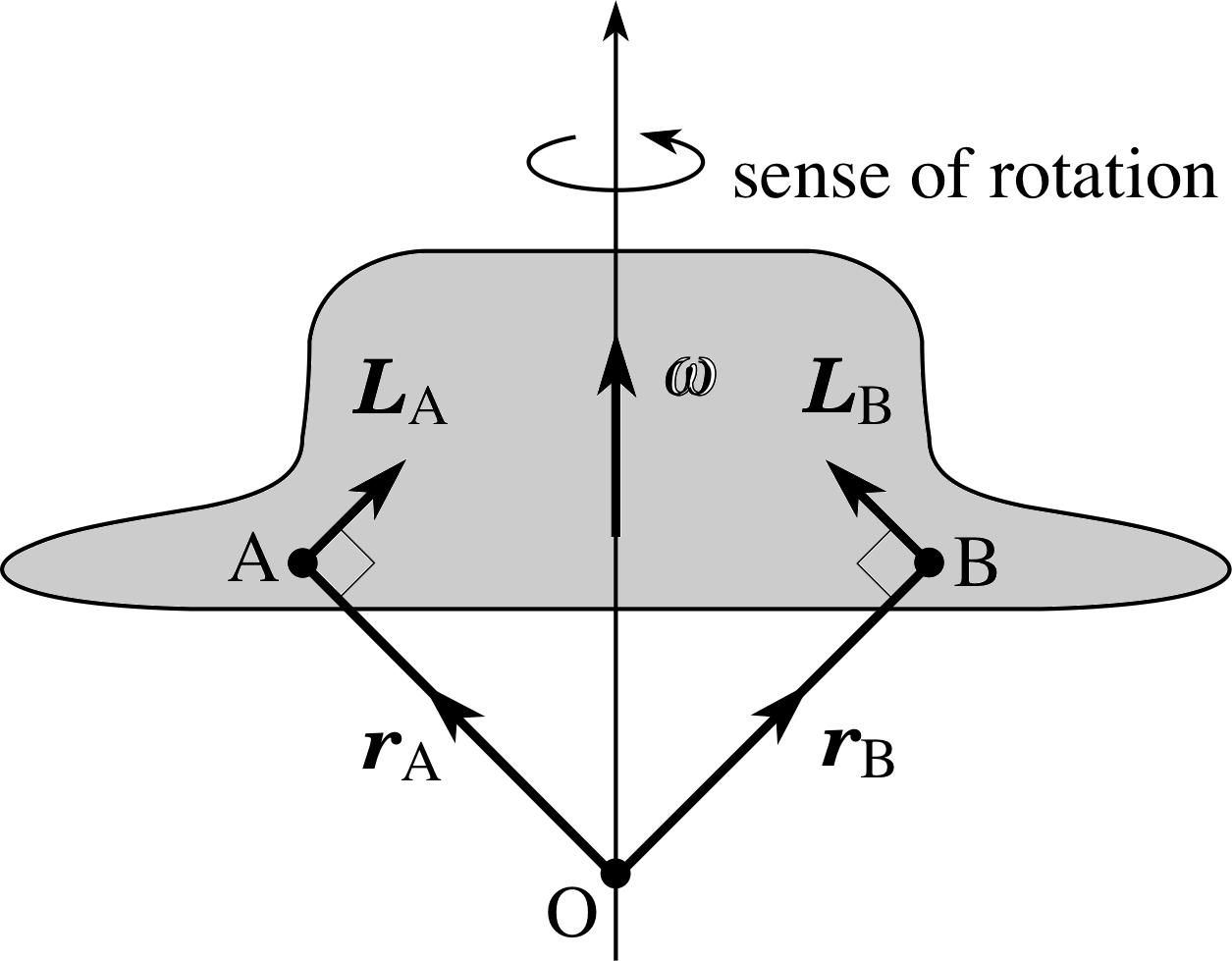
Figure 9 A body rotating about a symmetric axis. Particle A is in the plane (22) of the page and moving towards you; particle B is in the plane of the page and moving away from you.
You might also ask whether it is legitimate to use Equation 14b,
for an object $\dfrac{d\boldsymbol{L}}{dt}$ = Γ(Eqn 14b)
with L = Iω. The case of a body spinning about a symmetric axis deserves special mention here (Figure 9). Regarding the body as a collection of particles, we see that any particle A is matched by a similar particle B, such that the perpendicular components of the angular momentum of the pair of particles cancel out. Treating the whole body as a collection of such particle pairs it follows that the total angular momentum is parallel to the axis of rotation. So, in this case, we can write
rigid body, symmetric axis L = Iω(22)
At first sight, this result seems to be more general than others in this subsection, applying even if the axis of rotation changes. This is not really true. If the axis in Figure 9 were to swing away from the vertical there would inevitably be a sideways component of angular velocity, LωL hence the true axis of rotation would not remain symmetric and the argument which led to Equation 22 would not apply. In practice, you will sometimes see Equation 22 being used beyond its strict domain of validity, especially for bodies that spin rapidly about an axis that varies very slowly. Nevertheless, you should be aware that this involves an approximation. A lack of symmetry (or a varying axis of rotation) takes us back to the situation encountered in Equation 12:
L = r × p = (r|| + r⊥) × p = (r|| × p) + (r⊥ × p)(Eqn 12)
In general, L can have a component that is perpendicular to ω. So
| Translational motion | Rotational motion |
|---|---|
| p = (px, py, pz) | L = r × p = (ypz − z py, z px − x pz, x py − ypx) |
| F = (Fx, Fy, Fz) | Γ = r × F = (yFz − z Fy, z Fx − xFz, xFy − yFx) |
| dp/dt = F | dL/dt =Γ |
| If F = 0, then p is conserved | If Γ = 0, then L is conserved |
| p = mυ | If the axis is symmetric L = Iω |
| If the axis is fixed L|| = Iω | |
| m dυ/dt = F | If the axis is fixed I dω/dt = Γ|| |
L ≠ Iω
In spite of these warnings, strong similarities between rotational and translational motion persist and are summarized in Table 2. In many ways, the analogy is carried most safely and generally using (linear) momentum and angular momentum as in the third and fourth rows of the table. The special cases of symmetric and fixed axes allow us to go further, as in the last three rows, but this analogy is more dangerous because it has a narrower domain of validity.
5 Examples of rotational dynamics
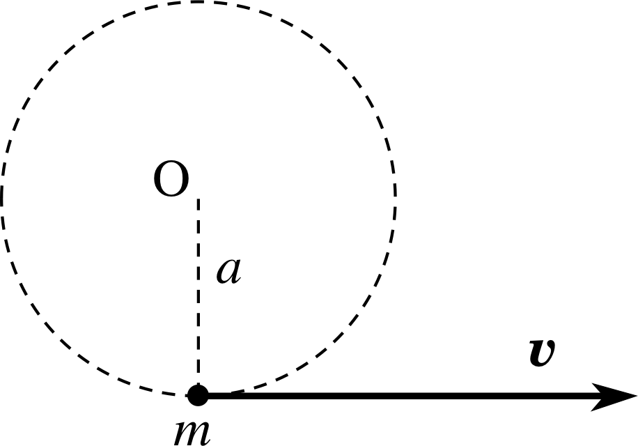
Figure 10 A particle is initially in uniform circular motion about the origin O. What happens to its angular momentum and angular speed after the string is cut?
The general principles developed in the previous section lead to some fascinating results. In this section we will look at many examples of rotational motion in order to illustrate how the general theory is used in practice.
5.1 Circular and linear motion
When a particle of mass m is attached to a string and swung round in a circle of radius a at speed υ we have no difficulty in assigning an angular speed or angular momentum to the particle. What happens if the string that supplies the centripetal force is cut? Physically, the particle flies off at a tangent and, in the absence of any forces, travels in a straight line at the constant speed υ (Figure 10). What can we say about its angular speed and angular momentum after the string has been severed?
Question T10
Relative to an origin at the centre O of the circular orbit, derive expressions for the magnitude of the angular momentum and the angular speed of the particle at a time t after the string is cut, if no forces act on the particle.
Answer T10
Before the string is cut the angular momentum of the particle about O has magnitude | L | = | r × p | = mυa. The act of cutting the string applies no torque to the particle, and no forces or torques act thereafter so the angular momentum of the particle remains constant and has magnitude mυa during its straight–line motion after the string is cut.
Comment: Note that angular momentum is associated even with straight–line motion, provided the straight line does not pass through our chosen origin. This means that angular momentum is more general than rotational motion. You may find this surprising but it is precisely this generalization that enables us to construct simple laws like the conservation of angular momentum – there is no law of conservation of angular velocity!
Nevertheless, the angular velocity of the particle does not immediately drop to zero when the string is cut. Suppose the string is cut at time t = 0, when the angular position of the particle is θ0. Then the angular position of the particle at some later time t is θ (t) = θ0 + ϕ (t) where
tan ϕ (t) = (distance travelled by particle/radius of circle) = d/a = υt/a
Differentiating this expression gives
$\dfrac{d(\tan\phi)}{dt} = \sec^2\phi\dfrac{d\phi}{dt} = \dfrac{\upsilon}{a}$
Thus
$\dfrac{d\phi}{dt} = \dfrac{\upsilon}{a}\cos^2\phi =\dfrac{\upsilon}{a} \times \dfrac{a^2}{a^2+\upsilon^2t^2} = \dfrac{\upsilon a}{a^2+\upsilon^2t^2}$
The angular speed is therefore
$\omega = \left\lvert\,\dfrac{d\theta}{dt}\,\right\rvert = \left\lvert\,\dfrac{d\phi}{dt}\,\right\rvert = \dfrac{\upsilon a}{a^2+\upsilon^2t^2}$
When the string is cut at t = 0, the angular speed is ω = υ/a, the value for uniform circular motion; this angular speed drops towards zero as the particle moves further away from the origin. The fact that ω depends on time means that there is an angular acceleration, in spite of there being no forces or torques. This again illustrates the dangers of using Equation 21 outside its domain of validity!
$\dfrac{d(I\boldsymbol{\omega})}{dt}$ = Γ|| (uni-axial rotation)(Eqn 21)
(Equation 21 only applies to the uni–axial rotation of a rigid body.)
5.2 Planetary motion and Kepler’s laws
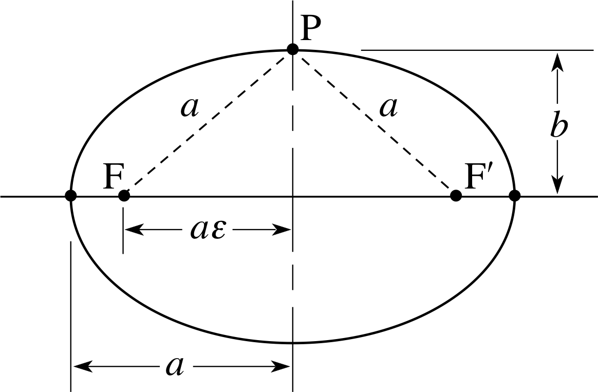
Figure 11 An ellipse can be traced out by plotting the locus of all points (P) such that the sum of the distances from two fixed foci (F and F′) is a constant. The ellipse is described in terms of a major axis of length 2a and a minor axis of length 2b. The ratio b/a = (1 − ε2)1/2, where ε is called the eccentricity of the ellipse.
In the early 17th century the German astronomer, Johannes Kepler (1571–1630) made a major advance in astronomy, based on an analysis of planetary data from the observations of the Danish astronomer Tycho Brahe (1546–1601). These data were very precise and a careful analysis persuaded Kepler to abandon the idea of circular orbits of the planets around the Sun, in favour of elliptical orbits, with the Sun at one focus of the ellipse. i In 1609 Kepler published his first two laws of keplers_laws_of_planetary_motionplanetary motion, and in 1619 he added a third:
- Kepler’s first law: Every planet moves around the Sun in a planar orbit that is an ellipse, with the Sun located at one focus. i
- Kepler’s second law: A straight line from the Sun to the planet sweeps out equal areas in equal time intervals.
- Kepler’s third law: The ratio of the square of the period of a planet in its orbit to the cube of the length of the semi–major axis of its orbit is the same for all planets.
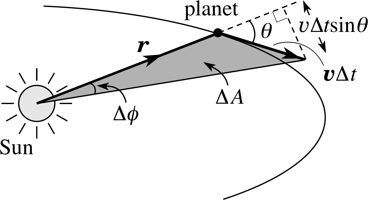
Figure 12 Geometrical construction for Kepler’s second law: hatched area = ½ base × height of triangle = ½ r (υ∆t sin θ)
Kepler’s second law is of particular significance for this module since it is a consequence of the law of conservation of angular momentum. Figure 12 shows a section of a planetary orbit with the Sun at one focus of the ellipse. During a short time interval ∆t, the position vector of the planet from the Sun moves through an angle ∆ϕ and sweeps out an area ∆A which can be approximated by
∆A = ½ r (υ∆t sin θ)
where υ is the speed of the planet and θ is the angle shown in Figure 12.
This approximation becomes increasingly accurate as the time interval is reduced. In the limiting case of a vanishingly small time interval the rate of change of area swept out by the planet is
$\displaystyle \dfrac{dA}{dt} = \lim_{\Delta t\rightarrow 0}\left(\dfrac{\Delta A}{\Delta t}\right) = \textstyle \frac{1}{2}r\upsilon\sin\theta$
Using the definition of angular momentum about an origin at the centre of the Sun, | L | = r υ r sin θ, we therefore have
$\dfrac{dA}{dt} = \dfrac{\lvert\,\boldsymbol{L}\,\rvert}{2m}$(23)
So, it is the angular momentum that controls dA/dt. The only force acting on the planet is due to the Sun’s gravitational pull whose line of action always passes through the Sun. This central force produces no torque about our origin so the law of conservation of angular momentum can be applied. This tells us that angular momentum about the Sun must be a constant vector hence dA/dt must also be constant, which is Kepler’s second law.
Conservation of angular momentum under a central force is the general principle behind Kepler’s second law. i
Aside Kepler’s observational laws are not completely accurate because they assume that the Sun occupies a fixed point which can be used as a fixed origin. This is not true because the Sun itself experiences gravitational forces due to all the planets and therefore accelerates. Because of its very large mass the Sun’s acceleration is small and very little error is made by ignoring it; nevertheless Kepler’s laws should only be regarded as approximations, valid within a simplified model of the solar system.
A full treatment of the solar system is tremendously difficult i but the model of an isolated star, orbited by a single planet can be analysed in detail (this is the so–called two–body problem). In this case, the centre of mass of the star–planet provides a suitable origin and both bodies can be thought of as orbiting their common centre of mass. Kepler’s first two laws then take the modified form:
- Kepler’s first law (modified): The planet moves in an elliptical path, with the focus at the position of the centre of mass of the planet–star system.
- Kepler’s second law (modified): The position vector for a planet, measured from the centre of mass of the planet–star system, sweeps out equal areas in equal time intervals.
Question T11
An artificial satellite has an elliptical orbit around the Earth. Its distance from the centre of the Earth is 6800 km at its nearest point to the Earth (the perigee) and 10 200 km at its furthest point (the apogee). Assuming that the Earth remains stationary (as its mass is so large compared to that of the satellite) calculate: (a) the ratio of the magnitudes of the angular momentum of the satellite about the Earth centre at perigee to that at apogee; (b) the ratio of the speed of the satellite along the orbital path at perigee to that at apogee.
Answer T11
(a) The gravitational force exerted by the Earth on the satellite is a central force so it exerts no torque about an origin centred on the Earth. The angular momentum of the satellite about the centre of the Earth is therefore conserved and the ratio of the angular momentum at perigee to that at apogee is 1.
(b) At perigee and at apogee, the velocity of the planet is perpendicular to the position vector from the Earth to the satellite. The magnitude of the angular momentum is therefore given by mυr. From part (a) we have
$\dfrac{\upsilon_1 r_1}{\upsilon_2 r_2} = 1$
so the ratio of speed at perigee to apogee is
$\dfrac{\upsilon_1}{\upsilon_2} = \dfrac{r_2}{r_1} = \dfrac{10\,200}{6\,800} = 1.5$
5.3 A rigid dumb-bell
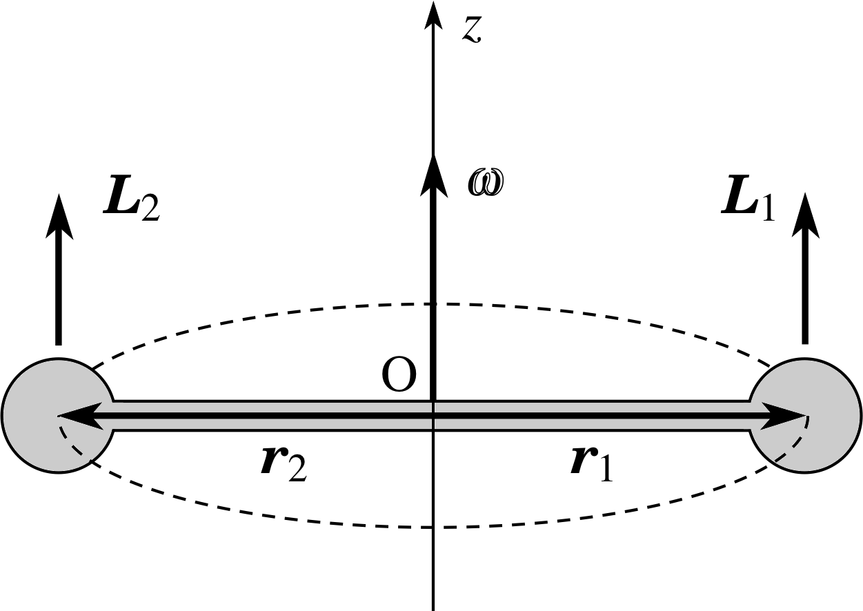
Figure 13 A symmetric dumb–bell rotating with angular speed ω about the central z–axis. At the instant shown, the masses are in the plane of the page; the left–hand mass is coming out of the page, towards you and the right–hand mass is travelling into the page, away from you.
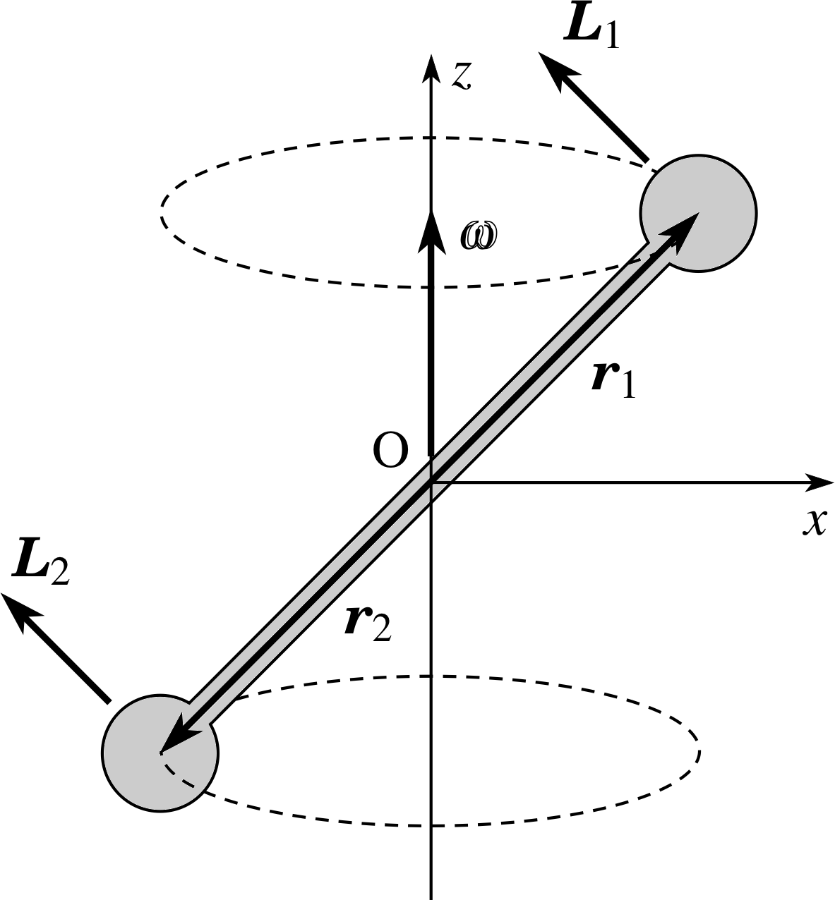
Figure 14 An asymmetric dumb–bell rotating with angular speed ω about the central z–axis. At the instant shown, the left–hand mass is moving out of the page towards you and the right–hand mass is moving into the page away from you.
Figure 6 The same motion as in Figure 5 but analysed using an origin O which is on the axis of rotation, but not in the plane of rotation. Relative to this new origin the position vector of the particle is r = r|| + r⊥ where r|| is a component vector along the axis of rotation and r⊥ is a component vector perpendicular to the axis of rotation.
We will now examine the rotational behaviour of rigid bodies. The important point about a rigid body is that its motion can always be described in terms of a translational motion of its centre of mass and a rotational motion of the whole body about an axis through the centre of mass. In general the axis may vary with time, but at each instant all the particles in the body have the same angular velocity about the same instantaneous axis of rotation – that is what being rigid implies.
Perhaps the simplest extended rigid body consists of two identical small objects, each of mass m, linked by a rigid rod of length 2r and negligible mass. Such a body is called a dumb-bell. Figure 13 shows the case of a symmetric dumb–bell in which the dumb–bell rotates at constant angular speed ω about its midpoint (O) and the rod joining the two masses lies in the plane of rotation. For the motion shown in Figure 13 the angular velocity points along the z-axis and the angular velocity vector is ω k. We choose our origin to be at the midpoint of the dumb–bell (which is its centre of mass). Then the angular momentum contributed by each mass is mr2ω k and the total angular momentum of the dumb–bell is found by adding together these contributions.
This gives
L = mr2ω k + mr2ω k = 2mr2ω k = Iω k
where the moment of inertia of the symmetric dumb–bell is given by
I = 2mr2
which is the sum of the moments of inertia of the individual masses. If no torques act on the dumb–bell its angular momentum will be conserved – it will carry on rotating at constant angular speed about the z–axis.
The behaviour of a symmetric dumb–bell is not very surprising and agrees with our earlier discussion of rotation about a symmetric axis. However, a very different situation arises if the rod joining the masses is tilted out of the plane of rotation to form an tilted symmetric dumb–bell as in Figure 14. Suppose that the dumb–bell is rotating with angular speed ω about the z-axis and that the origin is again chosen to be on the z–axis at the midpoint of the rod.
Then the right–hand rule shows that, relative to the origin O, each mass has an angular momentum in the direction shown (cf. Figure 6). i
The total angular momentum of the rod therefore has a component L|| along the z-axis which remains constant and a component L⊥ perpendicular to the z–axis which rotates around with the dumb-bell.
The existence of a time–varying component L⊥ has some interesting consequences. First, suppose that the dumb–bell is rotating steadily around the z–axis, as we have described above. Then the time–variation of L⊥ implies that dL⊥/dt ≠ 0 and Equation 14 shows that an external torque must be acting.
for an object $\dfrac{d\boldsymbol{L}}{dt}$ = Γ(Eqn 14b)
Such a torque could be provided if the z-axis were a physical shaft and the dumb–bell were attached to it by axial bearings. However, these torques would entail forces and hence friction and wear at the bearings. If possible, it would be preferable to avoid them by ensuring that the rotational axis is perpendicular to the rod axis, as in Figure 13, and that the tilt angle is zero. A similar problem occurs with a tilted dumb–bell if it is asymmetric, so that either m1 ≠ m2 or | r1 | ≠ | r2 |. Similar considerations apply to wheels, especially if the rotation rates are high. This is why special care is taken to ensure that car wheels and flywheels are not ‘out of balance’.
What would happen if no torques were applied to the tilted dumb–bell – for example, if the spinning dumb–bell were launched into the air and were subject only to the force of gravity? Gravity acts as if it were applied at the centre of mass O and so produces no torques about O. In this case, the law of conservation of angular momentum tells us that the total angular momentum of the spinning dumb–bell must remain constant.
✦ How can the total angular momentum of the dumb–bell remain constant when we have already seen that rotation around the z–axis entails a time–varying component vector L⊥?
✧ There must be another contribution to the angular momentum which cancels L⊥. At the instant shown in Figure 14, this additional contribution points along the x–axis and is associated with an additional rotation of the dumb–bell about a horizontal axis. The effect of this additional rotation is to cause the axis of rotation of the dumb–bell to wobble, so it cannot just rotate about a single axis if it is tilted.
Very similar effects occur when a spinning plate is thrown into the air (try it out if you have any plates you are tired of). To witness this effect, and understand its physical origins, illustrates the almost magical power of physics. i The wobbling of a spinning plate must seem deeply mysterious to the uninitiated – no amount of commonsense seems to explain it, but a physicist will happily account for the phenomenon on the back of an envelope.
5.4 The gyroscope
One of the most useful applications of angular momentum conservation is provided by the gyroscope. This is a wheel which spins rapidly about an axle, mounted on very low friction bearings, called gymbals. The gymbals allow the axle to maintain its direction, even if the support of the gyroscope and gymbals alters its orientation.
If the axle is initially pointing in a fixed direction, the angular momentum of the gyroscope points along the axle (which is an axis of symmetry). The gyroscope is normally mounted so that the gymbals support the weight of the gyroscope, but cause no torques about its centre of mass. Because the gyroscope experiences no external torque, its angular momentum is conserved and the axle maintains its initial orientation. This allows the gyroscope to be used as a navigational device on ships, aeroplanes, and spacecraft.
A gyroscope becomes even more wonderful when it is mounted in a different way, so that a torque does act on it. This can be achieved by moving the gymbals to one end of the gyroscope, so that relative to the fixed gymbals, the force of gravity provides an unbalanced torque. In this situation, the gyroscope undergoes a characteristic type of motion called precession, in which the axis of rotation swings around as if on the surface of a cone. i

Figure 15 (a) A gyroscope suspended at one end only, precessing about its support.
In the most perplexing example of precessional motion (Figure 15a), the spin axis is horizontal and precesses in a horizontal circle around the fixed gymbals. This is unexpected because we might expect the gyroscope to fall down under the gravitational force. Instead, the gymbals support the weight of the gyroscope while the gravitational torque causes the gyroscope to change its angular momentum, which is accomplished by changing the orientation of the axle.
We will now calculate the angular frequency of the precessional motion. In a short time ∆t the angle swept out by the axis of the gyroscope is ∆ψ (Figure 15b): because the angular momentum vector is swinging round the arc of a circle, the change in angular momentum has magnitude
| ∆L | = | L | ∆ψ = Iω ∆ψ

Figure 15 (b) Plan view of the motion of the gyroscope axis. Between t = 0 and t = ∆t the gyroscope gains angular momentum ∆L which has the same direction as the gravitational torque Γgrav.
Here we have made an approximation (of the kind we warned you about in Subsection 4.4). Because the gyroscope is assumed to spin rapidly about its axle, and to precess much more slowly than it spins, we have taken the angular momentum to point along the axle and to have magnitude Iω.
Dividing through by the time interval ∆t, we then have
$\left\lvert\,\dfrac{\Delta \boldsymbol{L}}{\Delta t}\,\right\rvert = I\omega\left\lvert\,\dfrac{\Delta \psi}{\Delta t}\,\right\rvert$
and, in the limit of a very small time interval,
$\left\lvert\,\dfrac{d\boldsymbol{L}}{dt}\,\right\rvert = I\omega\left\lvert\,\dfrac{d\psi}{dt}\,\right\rvert$
Finally, we can use the relationship between torque and angular momentum to deduce that
$\left\lvert\,\dfrac{d\boldsymbol{L}}{dt}\,\right\rvert$ = Γ = Mga
where M is the mass of the gyroscope and a the distance of the centre of mass from the support. Defining the precessional angular speed to be Ω = | dψ/dt |, we conclude that
Ω = $\dfrac{Mga}{I\omega} = \dfrac{\text{torque magnitude}}{\text{spin angular momentum magnitude}}$
You may come across several examples of gyroscopic motion in physics. In addition to the mechanical gyroscope discussed above, there is an ordinary top, the Earth spinning in the Sun’s gravitational field, a magnet spinning about its axis in a magnetic field, and a nucleus spinning in the magnetic field within the atom. All these precess about the direction in which they would experience no torque if the spin axis were aligned with this direction.
5.5 Other illustrations of angular momentum conservation
The spinning Earth
To a good approximation the Earth experiences no external resultant torque and so rotates with constant angular momentum. It spins about an axis of symmetry so its angular velocity remains constant; there are 24 hours in every day. This is not quite true, as there are two separate small astronomical effects which produce resultant torques on the Earth. First, the tides raised by the Moon’s gravity cause a very slight slowing down due to a frictional torque along the axis of rotation; the day is getting longer by about 2 milliseconds per century. Secondly, the fact that the Earth is not a perfect sphere, but bulges at the equator, and also that the plane of its spin differs from the plane of its orbit means that the gravitational influence of the Sun and Moon causes the axis of rotation to precess slowly, with a period of about 26 000 years.
A helicopter
When a helicopter is in mid–air it experiences negligible external torque so its total angular momentum is conserved. If the pilot changes the angular velocity and angular momentum of the overhead rotor blades the rest of the helicopter must change its angular momentum by rotating in the opposite sense. Clearly, it would not be desirable for the passenger and crew to go round in circles. To counteract this effect it is necessary to have a small propeller on the tail, or to use a pair of counter–rotating blades.
A spinning skater or a springboard diver
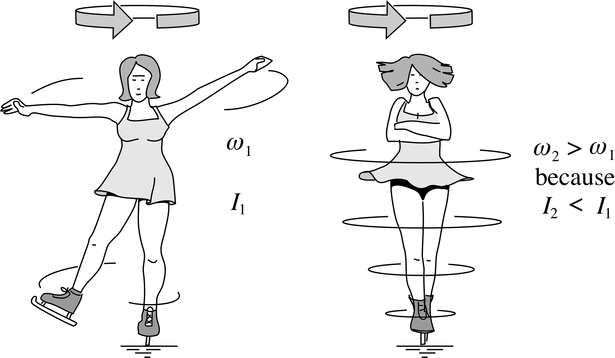
Figure 16 The angular speed of a skater increases when she raises her arms above her head or lowers them to her sides. Because her moment of inertia I decreases, her angular speed ω increases to ensure that her angular momentum L = Iω is conserved. You can experience a similar effect by extending your arms and legs while sitting on a rotating rotating swivel chair – but take care not to break a limb!
Both these examples can be modelled by articulated bodies (that is bodies that are made up of a small number of rigid parts which are free to move relative to one another). When a spinning skater pulls her outstretched arms inwards, towards her body, her angular speed increases (Figure 16). There is no resultant external torque about the skater’s centre of mass because the external forces (gravity and the upward reaction force from the ice) both have lines of action that pass through her centre of mass. The law of conservation of angular momentum then ensures that the skater has a constant angular momentum. The component of angular momentum parallel to the axis of rotation, Iω, is therefore constant.
By bringing her arms closer into her body, the skater reduces her moment of inertia, leading to an increase in her angular speed.
If her moment of inertia changes from I1 to I2 and her angular speed changes from ω1 to ω2 we have
I1ω1 = I2ω2
so her final angular speed is
$\omega_2 = \dfrac{I_1}{I_2}\omega_1$
A similar argument explains why a diver speeds up when he coils up in mid-air.
A falling cat
A falling cat is reputed always to land on its feet. High speed photography suggests that, even if its initial angular momentum is zero the cat rotates its tail rapidly to give the rest of its body a counter rotation so that it can land on its feet. Maybe the cat could not write down the equations, but it certainly understands the principles!
The birth and death of a star
One theory of the evolution of our solar system assumes that the Sun and the planets formed from a giant cloud of cosmic gas and dust, with some large scale rotation. As the cloud contracted under its own gravity, angular momentum was conserved and, as the distance of each particle from the centre of mass was decreased, the angular speeds of the particles increased. As a result, the whole mass rotated more rapidly. Because of local condensations the proto–solar system finally resolved itself into the Sun and a series of planets orbiting and spinning in roughly the same direction and with the same axis as the original angular momentum of the dust cloud.
Some massive stars will end their lives by collapsing to form very condensed neutron stars, with radii of only 10 – 15 km. These neutron stars show rapid flashes of light and radiowaves, caused by the neutron star rotating and sending out a beam of radiation, somewhat like a lighthouse. Such objects are known as pulsars. The rapid rotation of pulsars, which may have periods as short as a few hundredths of a second, is understood in terms of angular momentum conservation in the collapsing star (cf. the spinning skater).
Question T12
A turntable of mass 30 kg and radius 0.5 m is supported by an effectively frictionless bearing. A man of mass 70 kg standing at the centre of the turntable can be modelled as a solid cylinder of radius 0.15 m. He switches on a vertically directed high speed drill which is directly above his head. The drill rotates at 40 revolutions per second, and its rotating parts may be modelled as a solid cylinder of mass 200 g and radius 2 cm. Estimate the resulting angular speed of rotation of the man + turntable. (A solid cylinder of mass M and radius a has a moment of inertia ½ Ma2).
Answer T12
Take the system to be turntable + man + drill. Let the turntable have mass M, radius a and moment of inertia I; let the man have mass m1, radius a1and moment of inertia I1; let the working parts of the drill have mass m2, radius a2 and moment of inertia I2.
Before the drill is switched on, the total angular momentum of the system is zero. No external torques act on the system so the total angular momentum of the whole system remains zero when the drill is turned on. Concentrating on the component of angular momentum in the vertical direction,
0 = ½ Ma2ω + ½ m1a12ω − ½ m2a22ω2
where we have taken ω to be the shared angular speed of the man and the turntable and ω2 to be the angular speed of the drill. Thus:
$\omega = \left(\dfrac{m_2 a_2^2}{Ma^2+m_1a_1^2}\right)\omega_2 = \left[\dfrac{0.2\,{\rm kg}\times(0.02\,{\rm m})^2}{30\,{\rm kg}\times(0.5\,{\rm m})^2 + 70\,{\rm kg}\times(0.15\,{\rm m})^2}\right](40\times 2\pi\,{\rm rad\,s^{-1}})$
This gives ω = 2.2 × 10⁻³ rad s−1, which means that the turntable would rotate once in 48 min – hardly noticeable!
Question T13
If our Sun were to collapse, without significant loss of mass, into a star of radius 5000 km, estimate the period of rotation of that star. The Sun’s mass is 1.99 × 1030 kg, the radius of the Sun is 6.95 × 10⁸ m and its period of rotation is approximately 25 days. i The moment of inertia of a sphere of radius a about a diameter is I = $\frac{2}{5}$ Ma2.
Answer T13
No external torque acts on the Sun so the total angular momentum is conserved. The Sun does not actually rotate like a solid body, but for the purposes of the present estimate we will assume that it rotates as a solid sphere before and after the collapse. Conservation of angular momentum gives L1 = L2 and I1ω1 = I2ω2.
Thus
$\frac{2}{5}Mr_1^2\omega_1 = \frac{2}{5}Mr_2^2\omega_2$
so that
$\omega_2 = \left(\dfrac{r_1}{r_2}\right)^2\omega_1\quad\text{and}\quad T_2 = \left(\dfrac{r_2}{r_1}\right)^2T_1$
thus
$T_2 = \left(\dfrac{5\,000\times10^2\,{\rm m}}{6.95\times10^8\,{\rm m}}\right)^2\times 25\,{\rm day}$ = 1.29 × 10⁻³ day = 112 s
6 Closing items
6.1 Module summary
- 1
-
In uniform circular motion, with the origin at the centre of the circle, many scalar quantities are constants of the motion. In addition, two vector quantities are constants of the motion – the angular velocity ω and the angular momentum L, both of which are directed along the Figure 6axis of the rotation.
- 2
-
The angular velocity vector has a magnitude equal to the angular speed ω and points along the axis of rotation in a sense determined by the right hand ruleright-hand grip rule.
- 3
-
The centre of mass of a body is the unique point such that any force directed through the point produces translation of the body but no rotation. The centre of mass moves through space just like a particle that experiences the resultant external force acting on the body.
- 4
-
Any vector such as F = (Fx, Fy, Fz) can be represented as F = Fx i + Fy j + Fz k where i, j and k are unit vectors along the coordinate axes.
- 5
-
The vector product or cross-product of two vectors a and b is written as (a × b) and is a vector whose magnitude is a b sin θ, where θ is the smaller of the angles between the two vectors. The direction of the vector product is perpendicular to both a and b in a sense determined by the right-hand rule. This definition means that
b × a = −a × b(Eqn 3)
- 6
-
In terms of unit vectors
a × b = (aybz − azby) i + (azbx − axbz) j + (axby − aybx) k(Eqn 6)
- 7
-
The angular momentum of a particle about a given origin O is given by the vector product L = r × p where r is the position of the particle relative to O and p is its momentum. The vector L has magnitude rp sin θ, where θ is the angle between r and p. It points in a direction perpendicular to r and p in a sense determined by the right–hand rule.
- 8
-
The angular momentum of an extended body is the vector sum of the individual angular momenta of its constituent particles.
- 9
-
Torque is represented by the vector product
Γ = r × F(Eqn 13)
where r is the position vector of the point of application of the force F relative to a chosen origin O. The vector Γ has magnitude rF sin θ, where θ is the angle between r and F. It points in a direction perpendicular to r and F in a sense determined by the right–hand rule.
- 10
-
The rotational motion of any object is governed by the law
$\dfrac{d\boldsymbol{L}}{dt}$ = Γ(Eqn 14)
where Γ is the resultant external torque acting on the object and L is its total angular momentum.
- 11
-
The law of conservation of angular momentum states that when no unbalanced external torque acts on a body, its angular momentum stays constant.
- 12
-
When a body rotates about a fixed axis the law of rotational motion can be expressed as
$\dfrac{d\boldsymbol{L}_\Vert}{dt}$ = Γ||(Eqn 17)
with
L|| = Iω(Eqn 18)
Γ|| = r⊥ × F⊥
The quantity I is called the moment of inertia of the body about the given axis of rotation. It measures the reluctance of the body to change its state of rotational motion. Regarding the body as a collection of N particles, where the ith particle has mass mi and is a distance (r⊥)i from the axis of rotation,
$\displaystyle I = \sum_{i=1}^N m_i(r_\perp)_i^2$(Eqn 19)
and for uni–axial rotation
$\dfrac{d(I\boldsymbol{\omega})}{dt}$ = Γ||(Eqn 21)
- 13
-
If a body rotates about a symmetrical axis of rotation its angular momentum is aligned with its angular velocity:
L = Iω(Eqn 22)
If the axis is not symmetrical, or changes its orientation, this simple result beaks down because the angular momentum has components perpendicular to the angular velocity.
- 14
-
14 Angular velocity and angular momentum can be associated with linear motion.
- 15
-
Kepler’s second law states that the line joining the planet to the Sun traces out equal areas in equal times; this observational law is a consequence of the conservation of angular momentum.
- 16
-
The law of conservation of angular momentum explains why an object that spins about an asymmetric axis also wobbles.
- 17
-
The gyroscope is an important instrument based on angular momentum conservation. When subjected to a gravitational torque the gyroscope precesses (its spin axis swings round in the vertical axis).
6.2 Achievements
Having completed this module, you should be able to:
- A1
-
Define the terms that are emboldened and flagged in the margins of the module.
- A2
-
For a particle or a rigid body, evaluate the angular velocity vector about a given axis of rotation and show its direction on a diagram.
- A3
-
Evaluate the angular momentum vector of a particle about a given origin and show its direction on a diagram.
- A4
-
For a particle or a rigid body rotating about a fixed axis, calculate the angular momentum component vector along this axis in terms of the angular velocity and the moment of inertia about the axis.
- A5
-
Express angular velocity and angular momentum in terms of unit vectors and use these expressions in calculations.
- A6
-
Evaluate the torque vector about a given origin and show its direction on a diagram.
- A7
-
Express torque in terms of unit vectors and use the expression in calculations.
- A8
-
Recall and use the vector expressions which relate torque to rates of change of angular momentum.
- A9
-
Describe planetary motion in terms of Kepler’s laws and show how the second law relates to angular momentum conservation.
- A10
-
Describe how conservation of angular momentum relates to some practical situations, including the behaviour of a gyroscope.
Study comment You may now wish to take the following Exit test for this module which tests these Achievements. If you prefer to study the module further before taking this test then return to the topModule contents to review some of the topics.
6.3 Exit test
Study comment Having completed this module, you should be able to answer the following questions, each of which tests one or more of the Achievements.
Question E1 (A2, A3 and A4)
According to one (classical) model of the hydrogen atom, a single electron is in uniform circular motion around a central nucleus. In the lowest energy state of this system the magnitude of the angular momentum of the electron about the nucleus is L = h/2π, where h is Planck’s constant, h = 6.63 × 10⁻³⁴ J s. Given that the radius of the orbit is a = 5.31 × 10⁻¹¹ m and that the mass of the electron is 9.11 × 10⁻³¹ kg, calculate: (a) the electron speed, (b) the electron angular speed, (c) the moment of inertia of the electron about the central axis through the nucleus. (d) Show the angular velocity and angular momentum vectors on a diagram (for an origin at the centre of the circular orbit). i
Figure 5 A particle of mass m undergoes uniform circular motion in the (x, y) plane. Relative to an origin O at the centre of the circle the particle has position vector r and its momentum is p
Answer E1
The orbital angular momentum about the nucleus is: L = r × p, with magnitude L = pa = mυa = h/2π.
(a) The electron speed is:
$\upsilon=\dfrac{h}{2\pi am}=\dfrac{6.63\times 10^{-34}\,{\rm J\,s}}{2\pi\times 5.31\times 10^{-11}\,{\rm m}\times 9.11\times 10^{-11}\,{\rm kg}}$ = 2.18 × 10⁶ m s−1
(b) The angular speed is
ω = υ/r = 2.18 × 10⁶ m s−1/5.31 × 10−11 m = 4.11 × 10¹⁶ rad s−1
(c) The moment of inertia of the electron about the orbit centre is
I = ma2 = 9.11 × 10−31 kg × (5.31 × 10−11 m)2 = 2.57 × 10−51 kg m2
(d) The diagram could be presented in the form of Figure 5, with both the angular velocity and angular momentum vectors indicted to be along the positive z–axis.
(Reread Subsections 2.1 and 4.2 if you had difficulty with this question.)
Question E2 (A3, A4 and A10)
A student in a swivel chair, holding at arms length two skittle bowls, each of mass 4.5 kg, is spun at a speed of 1.0 revolution per second. He quickly brings the bowls to his waist. Estimate the final speed of rotation. You may assume that the moment of inertia of the student and swivel chair (excluding the bowls) is 7 kg m2 and you may ignore friction. i
Answer E2
No torques act on the system of student + chair + bowls so the law of conservation of angular momentum applies:
L = (I1 + I2)ω1 = (I1 + I ′ 2)ω2
where I1 is the moment of inertia of the student + chair, I2 is the initial and I ′2 the final moment of inertia of the bowls; ω1 and ω2 are the initial and final angular speeds. We can estimate that the bowls are initially 90 cm, and finally 15 cm from the axis. Then the final angular speed is:
$\omega_2 = \dfrac{I_1+I_2}{I_1+I^\prime_2}=\left[\dfrac{7.0\,{\rm kg\,m^2}+2\times 4.5\,{\rm kg}\times (0.9\,{\rm m})^2}{7.0\,{\rm kg\,m^2}+2\times 4.5\,{\rm kg}\times (0.15\,{\rm m})^2}\right]\times 2 \pi\,{\rm rad\,s^{-1}}$
so ω2 = 12.5 rad s−1 or 1.99 rev s−1
Don’t worry if you used different values for r1 and r2: it is the principle here that’s important, not the absolute value.
(Reread Subsections 4.3, 4.4 and 5.5 if you had difficulty with this question.)
Question E3 (A6 and A7)
A model aircraft is tethered to a post and moves along a circular path in the (x, y) plane with centre O and radius r. The engine exerts a force of magnitude F in a direction which is along the path. Air resistance may be ignored. Relative to the origin at O and using unit vector notation, write down expressions for (a) the resultant torque vector about O; (b) the change of angular momentum of the aircraft about O during a short time interval ∆t.
Figure 2 A particle undergoing uniform circular motion. The z–axis points out of the page, towards you.
Answer E3
(a) If the rotation in the (x, y) plane is as shown in Figure 2 then the force F is a vector in the direction of υ and the torque around the axis of rotation is Γ = r × F, which is directed out of the plane of the figure, along the positive z–axis, and has magnitude rF. In terms of unit vectors this is written as: Γ = rF k.
(b) Over a short time interval ∆t Equation 14b,
$\dfrac{d\boldsymbol{L}}{dt}$ = Γ(Eqn 14b)
can be expressed in the form
Γ = $\dfrac{d\boldsymbol{L}}{dt} = \dfrac{\Delta \boldsymbol{L}}{\Delta t}$
so the required change in angular momentum is ∆L = Γ∆t = rF∆t k.
(Reread Subsection 4.3 if you had difficulty with this question.)
Question E4 (A3, A4 and A10)
A student, sits on a swivel chair and holds a heavy–duty electric fan above his head. Initially, the student is at rest and the fan is rotating at a speed of 50 revolutions per second about a horizontal axis. He slowly turns the fan so that it is rotating clockwise about a vertical axis as viewed from below. Determine the magnitude and direction of the angular velocity of the student and chair after the fan has been turned, assuming that friction is negligible. You may take the moment of inertia of the fan about its axle to be 0.1 kg m2 and that of the student plus the swivel chair to be 3 kg m2. What happens if the student turns the fan so that it again rotates about a horizontal axis, but with the opposite angular velocity to that at the outset?
Answer E4
Initially the vertical component of the angular momentum of the student + chair + fan system is zero, since the axis of rotation of the (symmetrical) fan is horizontal. Throughout the process of moving the fan no external torque acts on the whole system so the vertical component of the angular momentum of the system must remain zero. In the final position, the fan rotates about a vertical axis, in a clockwise direction, as seen from below, so it has positive component of angular momentum along the upward vertical axis. To conserve angular momentum along this axis the student and chair must have an equal but opposite angular momentum along this axis and so must rotate anticlockwise as seen from below.
Let I1and ω1 be the moment of inertia and angular speed of the fan and let I2 and ω2 be the moment of inertia and final angular speed of the student plus chair. Then the law of conservation of angular momentum gives
0 = I1ω1 − I2ω2
Thus
$\omega_2 = \dfrac{I_1}{I_2}\omega_1=\dfrac{0.1\,{\rm kg\,m^2}}{3\,{\rm kg\,m^2}}(2 \pi\times 50\,{\rm rad\,s^{-1}})$ = 10.5 rad s−1 (i.e. 1.67 rev s−1)
When the student returns the fan so that it rotates about a horizontal axis its angular momentum along the vertical axis returns to zero; so too must that of the student plus chair and so his rotation stops, irrespective of the manner in which he returns the fan to a horizontal axis of rotation.
(Reread Subsections 4.3 and 5.5 if you had difficulty with this question.)
Question E5 (A6, A8 and A10)
Explain as fully as you can why a coin, rolling rapidly on a pavement, is stable against small surface irregularities.
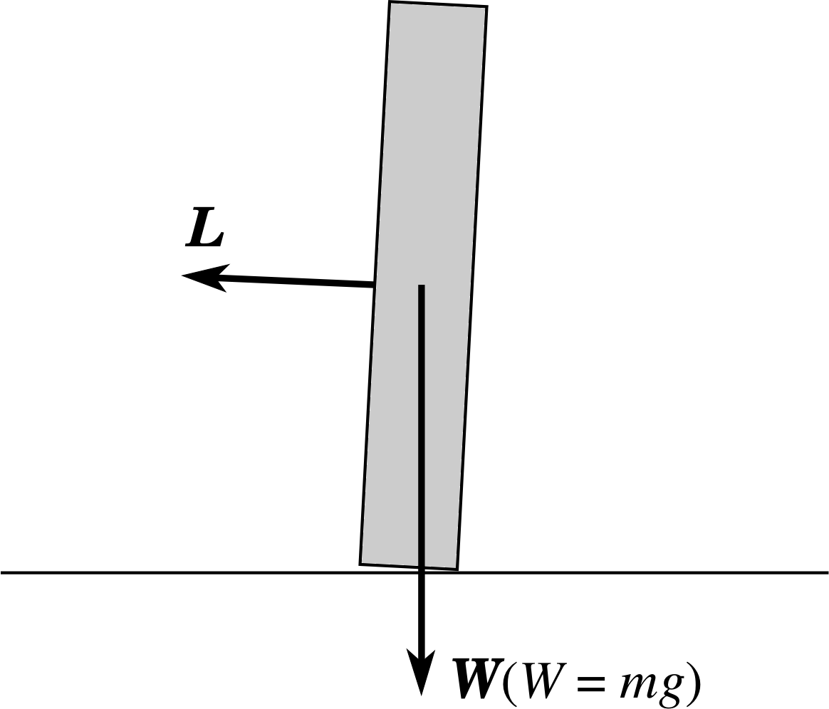
Figure 18 See Answer E5.
Answer E5
Suppose that a surface irregularity causes the centre of mass of the coin to suddenly overhang its base a little (Figure 18). If the coin were at rest it would topple, but it has angular momentum around (an almost) horizontal axis and the gravitational torque about the line of contact of the coin with the ground is along a perpendicular horizontal axis (into the plane of the page in Figure 18). The angular momentum will therefore change in the direction of the gravitational torque. This implies that the coil will veer to one side, but it will not topple. On the average surface, irregularities create gravitational torques equally to the right and to the left of the average direction of motion of the coin so that its average path is a straight line. The faster it rotates, the larger the angular momentum and the smaller the angle turned through needs to be to produce a given change in angular momentum in response to the surface.
(Reread Subsection 4.3 if you had difficulty with this question.)
Question E6 (A3, A4 and A10)
A roller skater of mass 60 kg, travelling at 10 km h−1 in a circle in the (x, y) plane is attached by a rope to a winch at the centre of the circle. He orbits in an anticlockwise sense as seen from above. The winch slowly winds in the rope, from an initial length of 15 m to a final length of 5 m. Friction is negligible. Using unit vector notation write down expressions for (a) the initial angular velocity vector, (b) the initial angular momentum vector, (c) the final angular momentum vector, (d) the final angular velocity vector.
Answer E6
Since the force from the winch is perpendicular to the velocity of the skater there is no tangential force and no torque applied about the centre of the path; the angular momentum of the skater must therefore remain constant as he is winched in. Let the mass of the skater be M, his initial angular speed and radius from the centre be ω1 and r1 and his final angular speed and radius be ω2 and r2.
(a) The initial angular speed is
ω1 = υ1/r1 = 2.78 m s−1/15 m = 0.185 rad s−1
The initial angular velocity vector has magnitude ω1. The skater spirals anticlockwise as seen from above so the right–hand rule shows that the angular velocity vector points vertically upwards. Taking this direction to be the z–axis we have
ω1 = 0.185 k rad s−1
(b) The initial angular momentum vector has magnitude
L1 = mυ1r1 = 60 kg × 2.78 m s−1 × 15 m = 2.50 × 10³ kg m2 s−1
and is directed upwards along the positive z–axis. Thus
L1 = 2.50 × 10³ k kg m2 s−1
(c) With no torques acting the final angular momentum must be the same as the initial angular momentum. Thus
L2 = 2.50 ×10³ k kg m2 s−1
(d) The final angular momentum has magnitude L2 = mr22ω2 so
ω2 = L2/ mr22 = 2.50 × 10³ k kg m2 s−1/[60 kg × (5m)2] = 1.67 k rad s−1
(Reread Subsections 2.1 and 4.3 if you had difficulty with this question.)
Question E7 (A5 and A10)
Two freewheeling roller skaters of equal mass M approach each other on parallel paths a distance b apart with opposite velocities, υ and −υ. As they pass each other they lock hands together. Using unit vector notation, obtain an algebraic expression for the final angular velocity of the skaters. Explain whether there is a change in the kinetic energy of the system? You may ignore friction at the skates.
Answer E7
Take the common centre of mass of the skaters, mid–way along the line connecting them, as the origin for calculating angular momentum. Since the skaters are freewheeling and friction may be ignored there is no external torque on the system and the total angular momentum before and after they unite is the same. Before the collision each skater has the same angular momentum of magnitude Mbυ/2 (see Answer T10). Hence
$L_1=2\times M\upsilon \dfrac{b}{2} = M\upsilon b = L_2$
but$L_1=L_2=I\omega=2\times M\left(\dfrac{b^2}{4}\right)^2\omega$
and therefore $\omega = \dfrac{2\upsilon}{b}$
Each skater has the same final speed υfinal = ωb/2 = 2υ/b × b/2 = υ. Since the speeds do not alter, the kinetic energies do not change either.
(Reread Subsections 4.3 and 5.1 if you had difficulty with this question.)
Question E8 (A4 and A10)
Given that the rotational kinetic energy of a body rotating with angular speed ω, about an axis about which its moment of inertia is I, is Iω2/2. Show that, for the example of the spinning skater, there must be an increase in kinetic energy when her arms are drawn inwards.
Answer E8
Since the rotational kinetic energy
Erot = ½ Iω2 = ½ (Iω)ω = ½ Lω
the kinetic energy of the skater must increase since L is conserved and ω increases. This increase comes from the mechanical work done by the centripetal forces which she applies in pulling her arms inwards.
(Reread Subsection 4.3 if you had difficulty with this question.)
Study comment This is the final Exit test question. When you have completed the Exit test go back and try the Subsection 1.2Fast track questions if you have not already done so.
If you have completed both the Fast track questions and the Exit test, then you have finished the module and may leave it here.
Study comment Having seen the Fast track questions you may feel that it would be wiser to follow the normal route through the module and to proceed directly to the following Ready to study? Subsection.
Alternatively, you may still be sufficiently comfortable with the material covered by the module to proceed directly to the Section 6Closing items.