PHYS 4.5: Energy in electric and magnetic fields |
PPLATO @ | |||||
PPLATO / FLAP (Flexible Learning Approach To Physics) |
||||||
|
1 Opening items
1.1 Module introduction
Since the mid-19th century our lives have been revolutionized by the application of electrical and magnetic principles. In this module, we consider how energy is stored in electric and magnetic fields.
For example, you may have wondered how an electronic flash gun in a camera stores its energy and is able to release it all almost immediately. In Section 2 you will see that we can explain this in terms of capacitance and energy stored by the charge in the electric field of a capacitor. We will consider how the shapes and sizes of capacitors, as well as the materials from which they are made, affect the amount of charge which can be stored, and also how combining capacitors in series and in parallel allows us to vary the charge stored and the potential difference across them.
Many electrical devices rely on energy being stored and released over a long period. Section 3 is about these energy stores – electric cells and batteries. You will see that the position of metals in the electrochemical series determines their behaviour in a cell, and that there are limitations including internal resistance and polarization that affect the design of cells and batteries.
Section 4 is about the magnetic fields associated with electric currents, and the energy stored in magnetic fields. We explain this in terms of inductance and it is the energy stored in the magnetic field due to a current in an inductor that is responsible for generating the high voltages required for the spark plugs in a car or the starter in a fluorescent tube.
Capacitors produce transient currents which change exponentially when a d.c. supply is suddenly switched on or off. Similarly, there is a short–lived induced voltage while the current in an inductor is changing. These transient phenomena are characterized by the capacitive or inductive time constant of the circuit. As you will see in Sections 2 and 4, the mathematical analysis of these effects can prove challenging but gives an insight into the behaviour of changing electric and magnetic fields. It is very satisfying that situations such as this can be modelled mathematically and give excellent agreement with the observed phenomena.
Study comment Having read the introduction you may feel that you are already familiar with the material covered by this module and that you do not need to study it. If so, try the following Fast track questions. If not, proceed directly to the Subsection 1.3Ready to study? Subsection.
1.2 Fast track questions
Study comment Can you answer the following Fast track questions? If you answer the questions successfully you need only glance through the module before looking at the Subsection 5.1Module summary and the Subsection 5.2Achievements. If you are sure that you can meet each of these achievements, try the Subsection 5.3Exit test. If you have difficulty with only one or two of the questions you should follow the guidance given in the answers and read the relevant parts of the module. However, if you have difficulty with more than two of the Exit questions you are strongly advised to study the whole module.
Question F1
Calculate the self inductance of an air–cored coil of length 5 cm and diameter 1.5 cm wound with 1000 turns. i This coil is found to have a resistance of 20 Ω. It is then connected to a 12 V d.c. supply. Calculate the energy stored in the magnetic field when it is fully established.
Answer F1
Self-inductance is given by L = μ0AN 2/l
so$L = \rm \dfrac{4\pi\times10^{-7}\,H\,m^{-1}\times\pi\times(0.75\times10^{-2}\, m)^2\times1000^2}{5\times10^{-2}\,m} = 4.4\times10\,H$
Energy stored = $\frac12 LI^2$, where $I = \dfrac VR = \rm \dfrac{12\,V}{20\,\Omega} = 0.6\,A$
Hence$E_{\rm mag} = \rm \frac12\times(4.4\times10^{-3}\,H)\times(0.6\,A)^2 \approx 8\times10^{-4}\,J$
Question F2
A 200 μF capacitor is charged by connecting it to a 100 V d.c. supply, and then discharged through a 500 Ω resistor. Draw an annotated sketch graph to show how the charge on the capacitor changes with time during the discharge. Make your sketch graph as quantitative as possible.
Answer F2
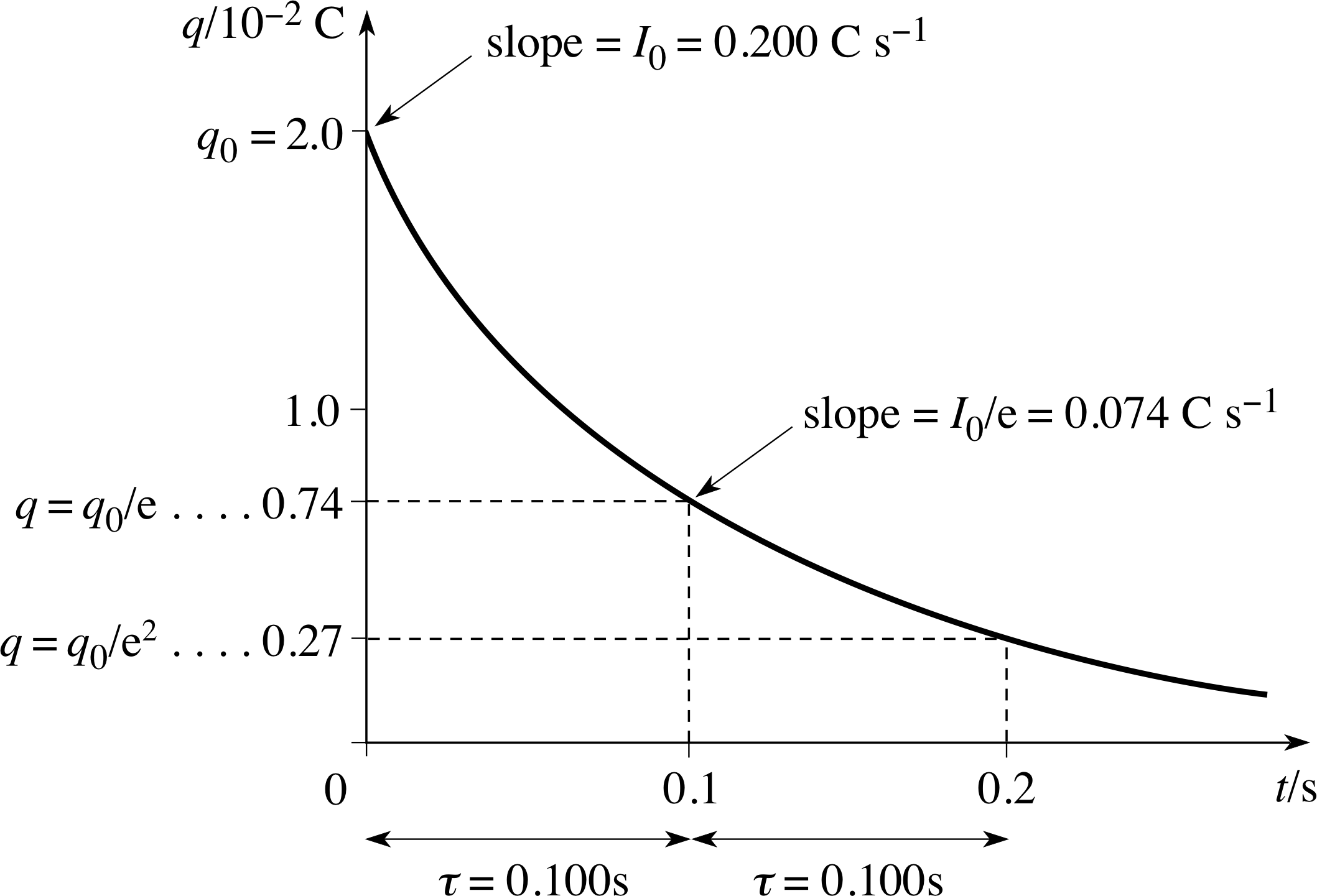
Figure 18 See Answer F2.
The graph is shown in Figure 18.
Initial charge:
q0 = CV0 = 100 V × 200 × 10−6 F = 2 × 10⁻² C
Initial current:
I0 = V0/R = 100 V/500 Ω = 0.2 A
The discharge is exponential:
q = q0e−t/RC, so after a time interval τC = RC,
q = q0/e ≈ 0.74 × 10⁻² C
For this circuit,
τ0 = RC = 500 Ω × 200 × 10−6 F = 0.1 s
The time interval τ0 = RC is the time constant of the discharge: in any interval of τ0, q is reduced by a factor e; the potential difference V across the capacitor and the current I in the resistor also fall by a factor e in each interval of τ0.
1.3 Ready to study?
Study comment To begin the study of this module you will need to be familiar with the following terms: atom, charge, current, electric field, electromagnetic induction, energy, ion, induced voltage, magnetic field, potential difference, resistance, voltage, work. If you are uncertain about any of these terms you can review them now by reference to the Glossary, which will also indicate where in FLAP they are developed. You will also need to have some understanding of self induction, although this topic is reviewed briefly in the course of the module. In addition, you will need to be able to sketch and interpret graphs, rearrange equations, use calculus notation for rates of change, recognize and interpret expressions for exponential change, differentiate simple exponential functions and evaluate definite integrals of the type $\int_a^bx\,dx$. The following questions will allow you to establish whether you need to review some of the topics before embarking on the module.
Question R1
Calculate the current in a 150 Ω resistor when there is a potential difference of 24 V across it. Hence calculate the power dissipated as heat in the resistor.
Answer R1
$I = \dfrac VR = \rm \dfrac{24\,V}{150\,\Omega} = 0.16\,A$
P = I 2R = (0.16 A)2 × (150 Ω) = 3.8 W
Consult circuitelectric circuits, current and voltage in the Glossary for further information.
Question R2
A potential difference of 3000 V is applied to two parallel plates that are held 15 mm apart. (a) What is the strength of the electric field between the plates? (b) How much work is done by the field if a charge of +2.0 μC moves from the positive to the negative plate? (c) What is the magnitude of the electrostatic force on this charge between the plates?
Answer R2
(a) Between parallel plates separated by a distance d, field strength has magnitude
E = V/d = 3000 V/0.015 m = 2.0 × 10⁵ V m−1
(b) Work done = qV = (2.0 × 10⁻⁶ C) × (3000 V) = 6.0 × 10⁻³ J
(c) The electrostatic force on a charge q in a field E has magnitude
Fel = qE = (2.0 × 10⁻⁶ C) × (2.0 × 10⁵ V m−1) = 0.4 N
Consult circuitelectric field and electric potential in the Glossary for further information.
Question R3
Explain the total voltage which results when three cells, each of voltage 1.5 V, are connected first of all in series and then in parallel.
Answer R3
For cells in series V2 = V2 + V2 + V2 = 4.5 V. We are able to sum the voltages since the negative terminal of one cell is at the same potential as the positive terminal of the next. However, when the cells are connected in parallel then the potential difference across the combination of cells is the same as the potential difference across any one cell, i.e. 1.5 V.
Consult potential difference and circuitelectric circuits in the Glossary for further information.
Question R4
Calculate the magnetic field strength at the centre of an air–cored solenoid of length 20 cm and diameter 2.0 cm if it has 600 turns and carries a direct current of 4 A. i
Answer R4
The expression for the magnetic field strength at the centre of a solenoid, whose length is much greater than its radius, is:
$B = \dfrac{\mu_0NI}{l} = \rm \dfrac{4\pi\times10^{-7}\,H\,m^{-1}\times600\times4\,A}{0.2\,m} = 15\times10^{-3}\,T$
Consult magnetic fields and currents in the Glossary for further information.
Question R5
The expression dA/dt = −kA describes how a quantity A varies with time, where k is a constant.
(a) Show that A = A0 e−kt, where A0 is a constant, is a solution to this equation.
(b) Write down expressions for the value of A when t = 0 and when t = 1/k.
Answer R5
(a) $\dfrac{dA}{dt} = \dfrac{d\left(A_0{\rm e}^{-kt}\right)}{dt} = A_0\dfrac{d{\rm e}^{-kt}}{dt}$
but, $\dfrac{d\left({\rm e}^{-kt}\right)}{dt} = -k{\rm e}^{-kt}$, and so $\dfrac{dA}{dt} =-kA_0{\rm e}^{-kt} = -kA$
(b) When t = 0, A = A0 (because e0 = 1); when t = 1/k, A = A0e−1 = A0/e.
Consult exponential functions in the Glossary for further information.
Question R6
Write down an expression for the value of $\displaystyle \int_0^{x_0}x\,dx$.
Answer R6
$\displaystyle \int_0^{x_0}x\,dx = \left[\dfrac{x^2}{2}\right]_0^{x_0} = \left(\dfrac{x_0^2}{2}\right) - \left(\dfrac{0^2}{2}\right) = \dfrac{x_0^2}{2}$
Consult integration in the Glossary for further information.
2 Capacitors
The first device we look at for storing energy is the capacitor. i
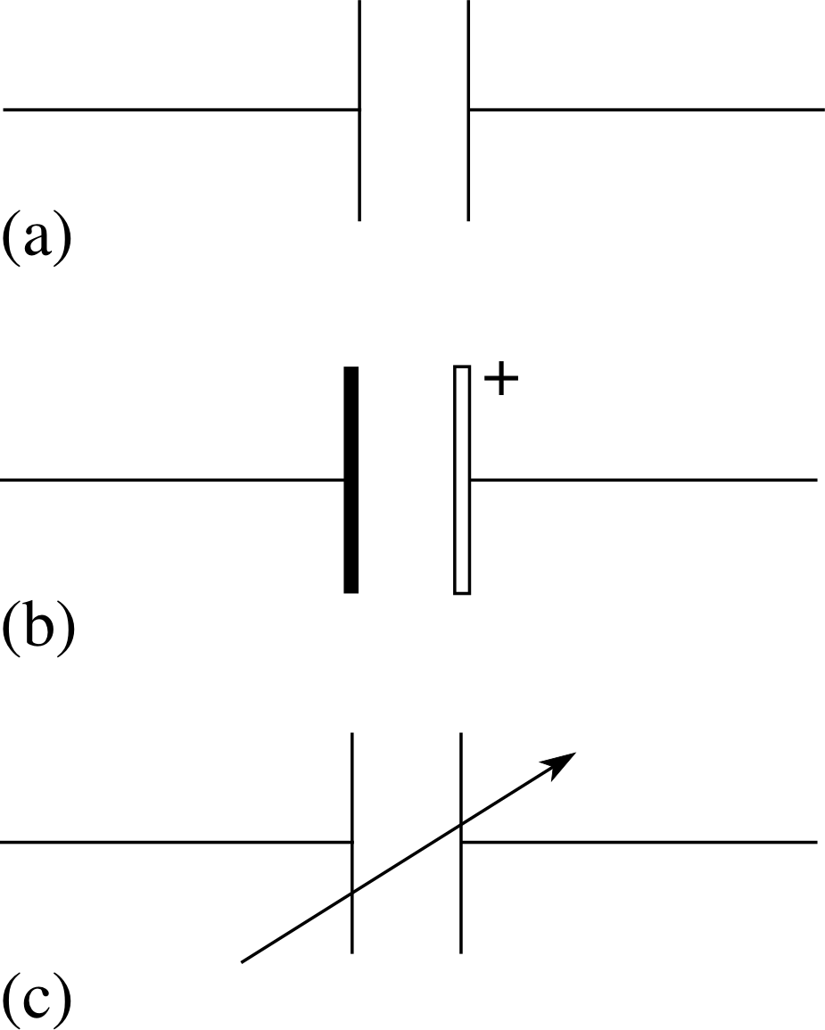
Figure 1 Circuit symbols for capacitors. (a) Any type of capacitor except electrolytic, (b) electrolytic capacitor, (c) variable capacitor.
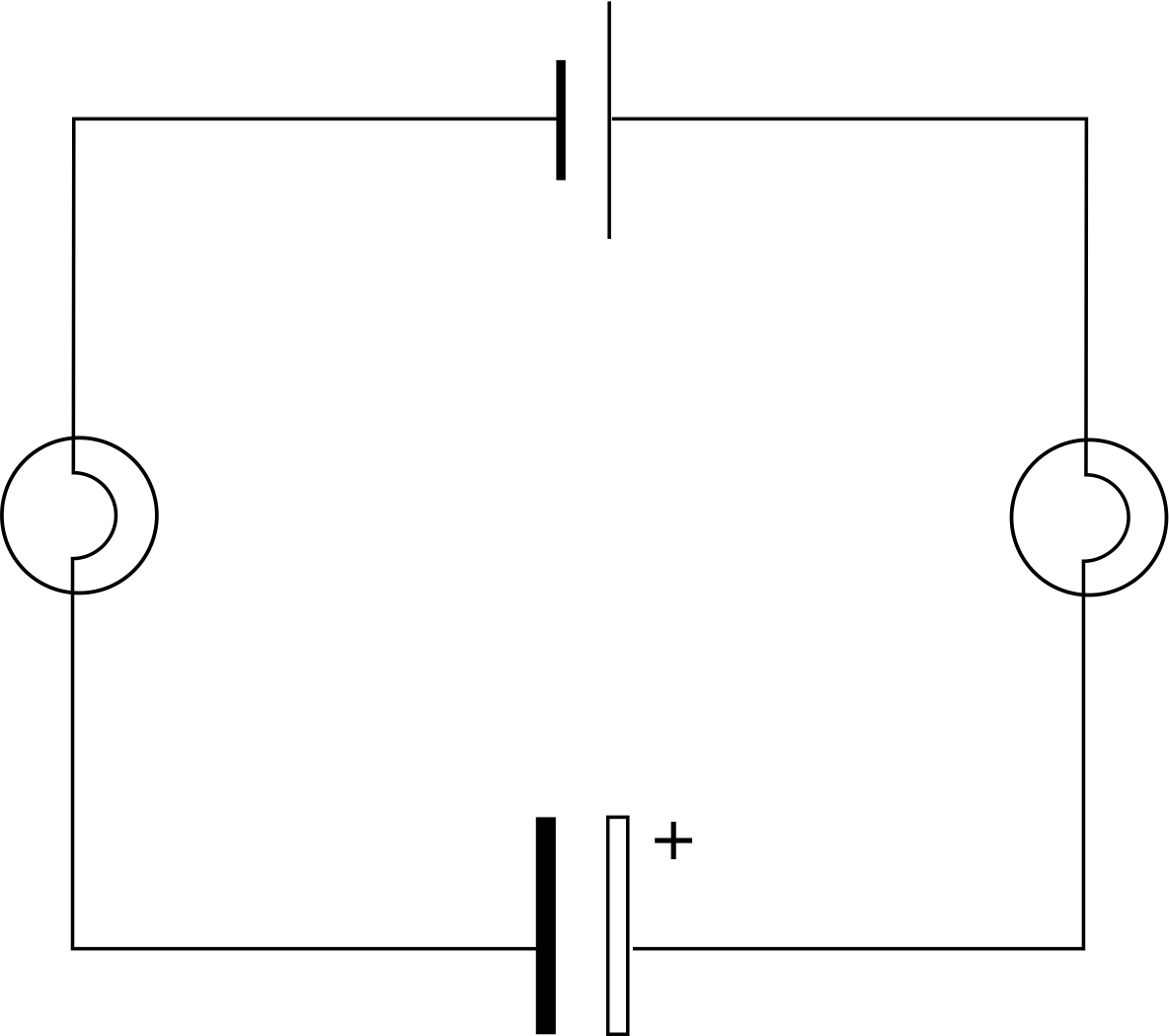
Figure 2 A capacitor being charged through light bulbs.
2.1 Capacitors and charge storage
A capacitor is a device for storing electrical charge. It is in essence a combination of two parallel metal plates separated by an insulating material – the dielectric.
Capacitors come in a variety of shapes and sizes. If you look inside any piece of electronic equipment you will see a range of capacitors. These will vary from small button–shaped devices to colourful metal cylinders. Inside a television or radio you may also find variable capacitors or tunable capacitors which may include a large collection of sliding plates with variable area of overlap. The terminals of some capacitors are labelled + and −, and it is important to connect these electrolytic capacitors the right way round in a d.c. circuit, i.e. with the terminal marked + at the more positive potential.
Figure 1 shows the circuit symbols for capacitors and Figure 2 shows a circuit containing an electrolytic capacitor.
Note If an electrolytic capacitor is connected the wrong way round in a circuit, chemical reactions take place within it that lead to heating and may even cause the capacitor to explode.
Despite the variety of designs we will try to keep things simple by describing capacitors as two parallel metal plates on which charge may be stored. The simplest way we can look at charge storage is to connect a capacitor in a circuit as shown in Figure 2. i When the switch is closed a current flows for a short time, lighting both bulbs, then the current rapidly falls to zero and so the bulbs dim and go out. This shows us two things:
- while the capacitor is charging, there is a current in the circuit;
- when the capacitor is fully charged there is no current.
Remember that current is the rate at which charge flows in a circuit. In most electrical circuits the charge which flows is in the form of negatively charged electrons. These are attracted from one plate towards the positive terminal of the supply giving that plate a net positive charge, this attracts an equal number of electrons to the other plate giving it an equal and opposite negative charge.
When we talk of the amount of charge, q, stored in a capacitor, we are really talking about a separation of charge, i.e. a charge +q on one plate and −q on the other. i
If you charge a capacitor through a bulb the variation in brightness of the bulb tells us that there is a high current soon after the connection is made but that this current dies away as it becomes progressively more difficult to add more charge to the plates. Eventually no more charge can be added and the capacitor is ‘fully charged’. i When the two charged plates are connected together electrons will flow to reduce the stored charge to zero and so the capacitor discharges. This means that if the capacitor is discharged through a bulb, then the bulb will be seen to glow briefly and then dim once the charge flow ceases. Alternatively, if the terminals of a charged capacitor are connected directly (without the bulb) then a spark may be seen.
Question T1
An amateur electrician decides to repair a faulty old television. Being cautious he switches it off and disconnects it from the socket. However, after a few moments of probing around with a screwdriver he is surprised to find that there is a blue flash and he burns his fingers. Suggest an explanation.
Answer T1
Many electrical devices contain capacitors. In the case of old televisions these can have quite large values and may retain their charge for some time after the set has been switched off and disconnected. If you touch the terminals of a charged capacitor, you may complete the circuit and allow charge to flow – in this case, the ‘electrician’ probably formed part of a complete circuit to earth.
A ‘fully charged’ capacitor is not ‘full’ in the same sense that a beaker can be full of liquid. If you increase the voltage across a ‘fully charged’ capacitor, more charge can be added to the plates. i The amount of charge q which gathers on the capacitor plates is proportional to the potential difference V across the plates: q ∝ V so we can write
q = CV(1)
where the constant C is the capacitance. If q is measured in coulomb and the potential difference V is in volts, then the capacitance is measured in farad (F), the SI unit of capacitance.
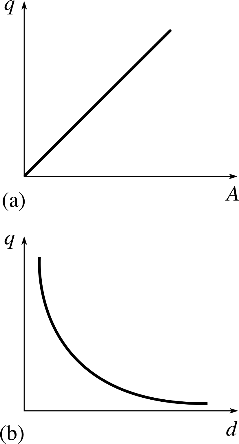
Figure 3 Graphs showing (a) q ∝ A (b) q ∝ 1/d.
The capacitance tells us how much charge can be stored per volt. 1 F = 1 C V−1. Capacitors used in electronic equipment typically have capacitances expressed in microfarads (μF), nanofarads (nF) or picofarads (pF). i The capacitance of a parallel plate capacitor depends upon three things:
- the area of overlap of the plates A;
- the distance separating the plates d;
- the dielectric material (insulator) between them.
If we measure charge stored in a capacitor as A and d are changed, for a particular value of voltage, the results are as shown in Figure 3.
We find that
- charge is directly proportional to the area of overlap q ∝ A;
- charge is inversely proportional to the plate separation q ∝ 1/d; and since C ∝ q, we deduce that C ∝ A/d.
| Material | Relative permittivity εr (at 251°C) |
|---|---|
| air | 1.000 536 |
| carbon dioxide | 1.000 922 |
| helium | 1.000 0650 |
| polyethylene | 2.35 |
| PVC | 4.55 |
| glass | 3.5 to 10 |
| ethanol | 24.30 |
| water | 80.37 |
We can include the effect of the dielectric by introducing a constant of proportionality ε, i known as the permittivity of the material and hence write the capacitance as
$C = \dfrac{\varepsilon A}{d}$(2) i
For a vacuum ε is equal to ε0 the permittivity of free space. i When other materials are used, ε0 is multiplied by the material’s dielectric constant or relative permittivity εr to give ε = εrε0.
Table 1 shows that there is quite a large variation in value of relative permittivity but that in general the values of εr for gases are approximately equal to 1.
In general, the expression for capacitance can be written:
$C = \dfrac{\varepsilon_r\varepsilon_0 A}{d}$(3)
Question T2
Two square metal plates, each of side 0.15 m, are placed on top of each other and separated by a layer of polyethylene 5.0 mm thick. What is the capacitance of the arrangement? Express your answer in pF.
Answer T2
Using Equation 3 and Table 1:
C = 2.35 × 8.854 × 10−12 F m−1 × (0.15 m)2/ 5.0 × 10⁻³ m = 9.4 × 10⁻¹¹ F = 94 pF
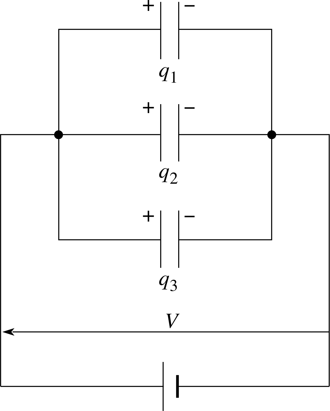
Figure 4 Capacitors connected in parallel.
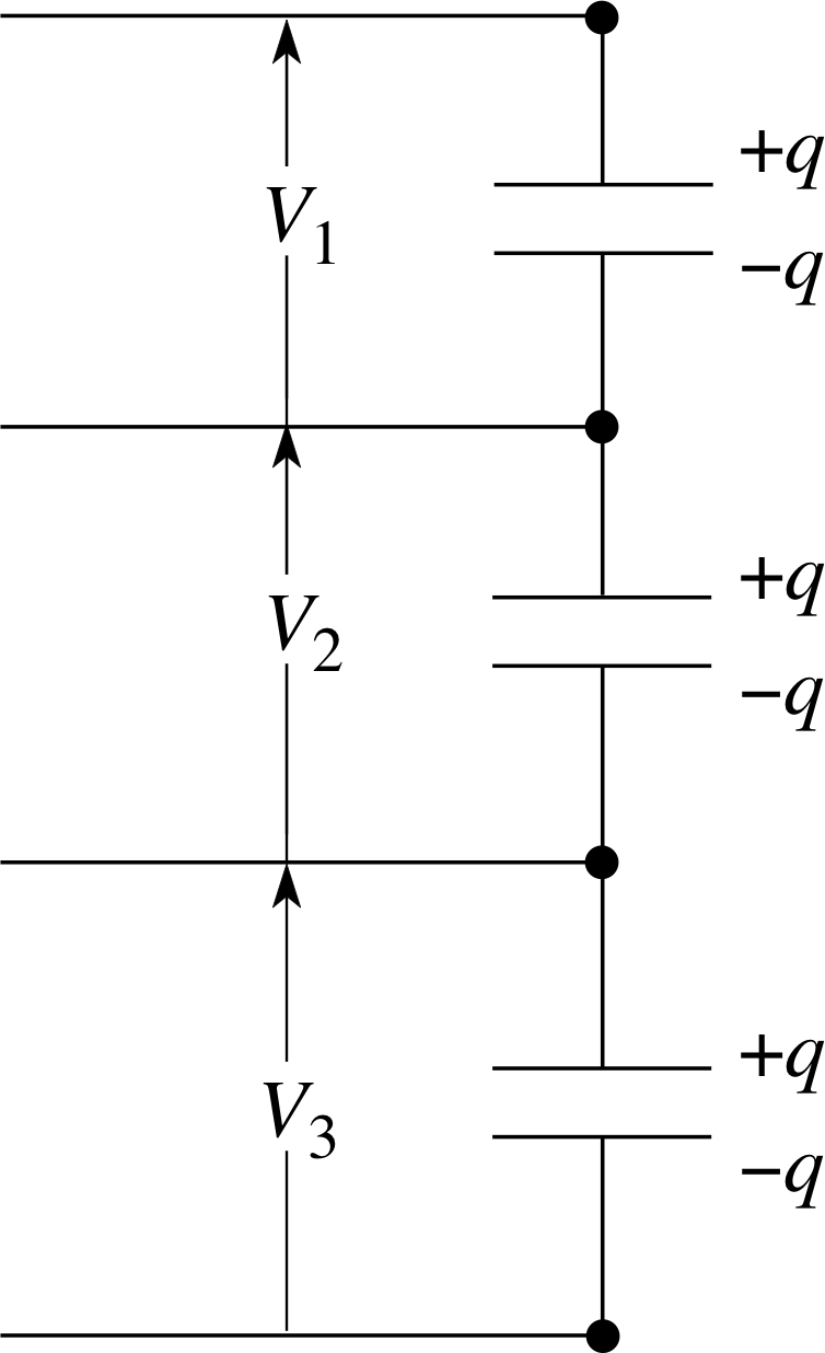
Figure 5 Capacitors connected in series.
2.2 Capacitors in series and parallel
Capacitors are mass–produced with a range of fixed capacitance values. In many practical circuits, capacitors are connected together in series or in parallel to produce values that are not available ‘off the shelf’. Figure 4 shows three capacitors connected in parallel so that each has the same potential difference V across its plates. The total charge stored, q, will be:
q = q1 +q2 +q3
soCV = C1V + C2V + C3V
i.e.CV = (C1+ C2 + C3)V
hence for capacitors in parallel, the total capacitance is the sum of the individual capacitances:
C = C1 + C2 + C3(4)
For the three capacitors connected in series (Figure 5) the total potential difference is given by the sum of the potential differences across each and, since charge can only be redistributed within the conducting parts of the arrangement, each capacitor stores the same charge q.
V = V1 + V2 + V3
Now, we can say V = q/C in each case, so we can write:
$\dfrac qC = \dfrac{q}{C_1}+\dfrac{q}{C_2}+\dfrac{q}{C_3}$
So, for capacitors in series, the reciprocal of the total capacitance is equal to the sum of the reciprocals of the capacitances:
$\dfrac 1C = \dfrac{1}{C_1}+\dfrac{1}{C_2}+\dfrac{1}{C_3}$(5)
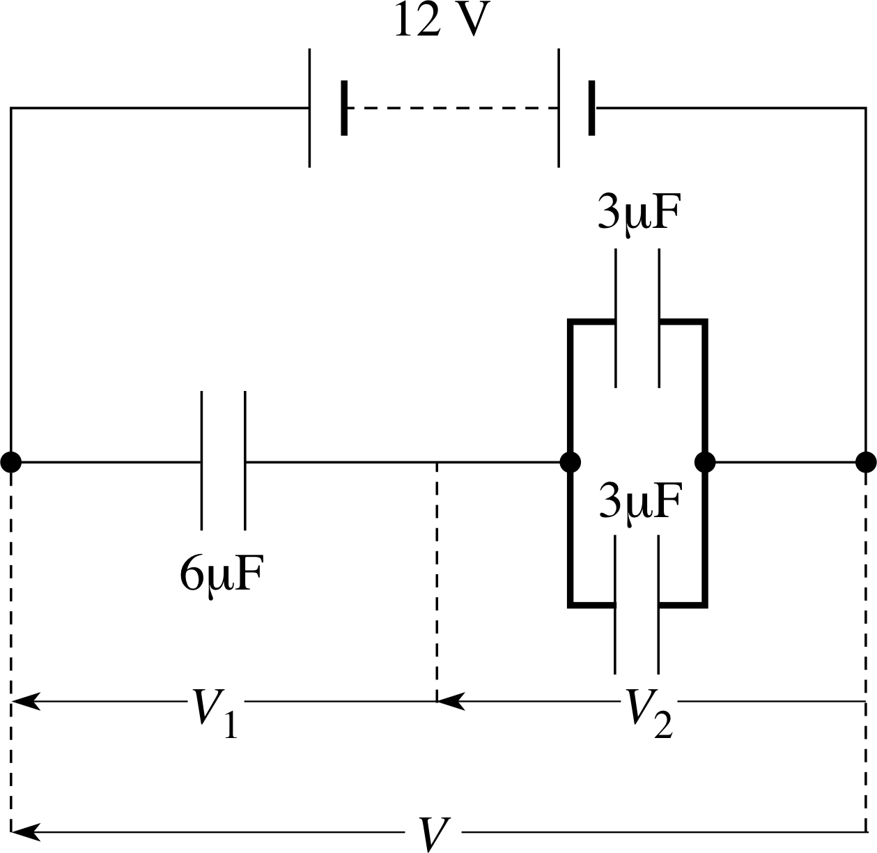
Figure 6 See Question T3.
Question T3
For the arrangement of capacitors in Figure 6 calculate the total capacitance and the potential differences V1 and V2.
Answer T3
For the two 3 μF capacitors in parallel
C = C1 + C2 = 6 μF
The whole arrangement is therefore equivalent to two 6 μF capacitors in series. Since the capacitances are equal V1 = V2 = 6 V
and$\dfrac1C = \rm \dfrac{1}{6\,\text{μ}F} + \dfrac{1}{6\,\text{μ}F}$
hence C = 3 μF.
2.3 Energy stored in capacitors and in electric fields
In a photographer’s flash gun, energy is first stored by charging a capacitor and then delivered to a bulb. Suppose a 10 000 μF capacitor is charged by connecting it to a 3 V battery. Equation 1,
q = CV(Eqn 1)
shows that the charge stored is 3 × 10⁻² C, but how can we calculate the energy delivered during the discharge? When the discharge begins, charge moves through a potential difference of 3 V – the capacitor is behaving, temporarily, like a 3V battery. If a small amount of charge ∆q moves through a potential difference V, the electrical energy transferred ∆Eel is given by
∆Eel = V∆q(6)
For a battery of steady voltage V, the total energy transferred by charge q would be Eel = Vq, but as the capacitor discharges its potential difference falls, so the last few electrons to flow around the circuit move through a voltage that is virtually zero. Since the voltage falls linearly as the charge falls it is the average voltage (V0/2) which should be used in this calculation. We could make a reasonable guess and say that the energy delivered would be the same as if all the charge moved through half the initial voltage V0, i.e. Eel = qV0/2. Using calculus techniques we can reach the same conclusion more rigorously, as we now show.
If we deal with small amounts of charge ∆q moving through a voltage V, the total energy transferred is the sum of all these small transfers of energy:
$E_{\rm el} = \sum V\,\Delta q$(7) i
Since q = CV, removing ∆q from the capacitor leads to a drop in voltage ∆V = ∆q/C, so ∆q = C∆V and hence
$E_{\rm el} = \sum CV\,\Delta V$(8)
If we make the changes infinitesimally small, and call the initial voltage V0, then we can replace the summation by an integral and the change in stored energy is
$\displaystyle E_{\rm el} = C\int_{V_0}^0V\,dV = -\dfrac{CV_0^2}{2}$(9)
The minus sign indicates that this amount of energy is lost by the capacitor.
Using Equations 1 and 9 we obtain three useful expressions for the energy Eel delivered during a capacitor discharge:
$E_{\rm el} = \dfrac12 \dfrac{q_0^2}{C} = \dfrac12q_0V_0 = \dfrac12CV_0^2$(10) i
Alternatively, we could use a similar argument to find the work done when a capacitor is charged. As the capacitor becomes progressively charged the rising potential difference means that more and more energy is needed to transfer a given amount of additional charge. If a small amount of charge ∆q is moved through a potential V then the energy transferred in moving this charge is ∆Eel = V∆q As charge builds up, V increases, and it becomes harder to move more charge into the capacitor. As before, the total energy transferred is the sum of all these small transfers, and the total energy transfer in charging is the same as the energy delivered during the discharge as described by Equation 10. The principle of energy conservation demands that these two energy transfers are the same.
Question T4
Calculate the energy stored when a 10 000 μF capacitor is connected across a 3 V battery. If the capacitor takes 1 ms to discharge fully through a bulb, estimate the average electrical power during the discharge. i
Answer T4
From Equation 10,
$E_{\rm el} = \dfrac12 \dfrac{q_0^2}{C} = \dfrac12q_0V_0 = \dfrac12CV_0^2$(Eqn 10)
energy stored = $\dfrac CV^2$ = 10 000 μF × (3 V)2/2 = 4.5 × 10⁻² J
Average power = energy transferred/time taken = 4.5 × 10⁻² J/10−3 s = 45 W
We can look at energy storage in a capacitor from another viewpoint. If a capacitor consists of two plates with area of overlap A, separated by a distance d, then Equations 2 and 10
$C = \dfrac{\varepsilon A}{d}$(Eqn 2)
$E_{\rm el} = \dfrac12 \dfrac{q_0^2}{C} = \dfrac12q_0V_0 = \dfrac12CV_0^2$(Eqn 10)
show that the energy stored is
Eel = AεV 2/(2d)(11)
Applying a potential difference V between two parallel plates gives rise to an electric field between the plates. We can relate the energy stored to the electric field strength. If there is a potential difference V between two plates separated by a distance d, but with no dielectric present, then between the plates there is a uniform electric field E of magnitude
E = V/d(12) i
This is the electric field in which the dielectric is placed. We can write this as V = Ed and hence substituting V 2 = E2d2 in Equation 11 gives
Eel = Adε E2/2(13) i
Study comment We must be rather careful in the wording here. We are on the edge of a topic which lies beyond FLAP. The point is that if a dielectric is placed in an electric field E the electric field within the dielectric is reduced by the factor εr, the relative permittivity or dielectric constant. This arises because of electric polarization in the dielectric, which in turn arises because of the electric dipole moments within the material which are induced by the applied field E. The topic of electric polarization lies beyond FLAP. Nevertheless, our expression (Equation 13) remains valid within the dielectric providing E is interpreted as the magnitude of the electric field in the region before the dielectric is inserted.
This may not look particularly interesting until we notice that Ad is the volume enclosed by the plates. The energy per unit volume is called the energy density, so
an electric field of magnitude E in which there is placed a dielectric material of permittivity ε has an energy density of εE2/2 within the dielectric.
This statement applies to any electric field – it need not be between capacitor plates, nor need it be uniform. In a non–uniform field, the local energy density varies with position just as the field strength varies.
2.4 Transient currents in capacitive circuits
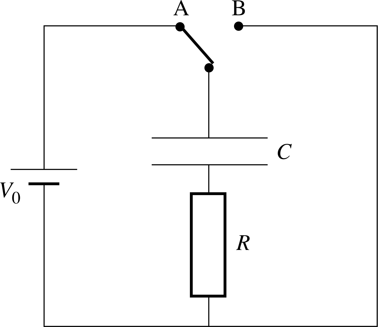
Figure 7 Circuit for charging and discharging a capacitor through a resistor. Switch at A: capacitor charges. Switch at B: capacitor discharges.
Figure 2 A capacitor being charged through light bulbs.
We have seen that when a capacitor is connected in a d.c. circuit there will be a current while the capacitor is charging or discharging. The fading brightness of the bulbs in Figure 2 suggests that the current does not remain steady during this time. In this subsection, we will derive mathematical expressions for this short–lived current known as a transient current.
Suppose a capacitor is charged by being connected to a battery through a circuit of resistance R so that initially the charge is q0 = CV0. Suppose it is then discharged through a resistor R. Figure 7 shows a suitable circuit for both the charging and discharging.
During the discharge, q decreases and hence V also decreases – as discussed in Subsection 2.3, the capacitor behaves like a battery whose voltage is rapidly falling. We can write down two expressions for the current, I, in the circuit. The current I is equal to the rate of flow of charge so, in calculus notation
$I = -\dfrac{dq}{dt}$(14) i
We also know that when there is a potential difference V across a resistor R, I = V/R. Substituting V = q/C (from Equation 1) i,
q = CV(Eqn 1)
we can write
$I = \dfrac{q}{RC}$(15)
Comparing Equations 14 and 15 we can write
$\dfrac{dq}{dt} = -\dfrac{q}{RC} = -\dfrac{1}{RC}q$(16)
✦ If q decreases such that its rate of change is proportional to the remaining charge (i.e. dq/dt ∝ q), what law of change is involved?
✧ The charge follows an exponential law, as shown in Question R5.

Figure 8b Charging curve for a capacitor.

Figure 8a Discharge curve for a capacitor.
Since the proportionality constant is negative, i.e. q is decreasing with time, we have an example of exponential decay. In this particular case, the decay constant is −1/RC so we can write down an expression for q at any time t:
q (t) = q0 e−t/RC(17) i

Figure 8d Charging current.

Figure 8c Discharge current.
Equation 17 gives the exponential decay curve shown in Figure 8a. The early steep i gradient shows that the early current is large, then it dies away, rather as we might expect from observing circuits like Figure 2.
Figure 8b shows how the charge builds up when the capacitor is being charged through a resistor – it is the curve in Figure 8a flipped over. Again, the early current is large, then it dies away.
The discharging current is shown in Figure 8c and the charging current in Figure 8d. These two curves are given by the negative of the gradients of Figures 8a and 8b, respectively, from Equation14,
$I = -\dfrac{dq}{dt}$(Eqn 14)
Notice the charging current is in the opposite direction to the discharge current.
While the capacitor is charging, the net potential difference across the resistor is V0 − V, where V0 is the battery voltage and V the voltage due to the partially–charged capacitor. The current is therefore given by I = (V0 − V)/R and hence
$\dfrac{dq}{dt} = \dfrac{q_0 - q}{RC}$(18)
In Question T5 you can confirm that the corresponding expression for the charge at time t is:
$q = q_0\left(1 - {\rm e}^{-t/RC}\right)$(19)
Question T5
According to Equation 19, what is the charge when t = 0? What is q when t is very large? Are these values what you would expect? By differentiating and rearranging Equation 19, show that it is a solution of Equation 18.
Answer T5
When t = 0, e−t/RC = e0 = 1 and hence q = 0. When t is very large, e−t/RC ≈ 0 and so q ≈ q0. Both these values are as you would expect for a charging capacitor.
Differentiating Equation 19 we have
$\dfrac{dq}{dt} = \dfrac{1}{RC}q_0{\rm e}^{-t/RC}$
and rearranging Equation 19 we have
$q_0 - q = q_0{\rm e}^{-t/RC}$
Hence$\dfrac{dq}{dt} = \dfrac{q_0-q}{RC}$ as required by Equation 18.
The product RC has the dimensions of time. You can see this by comparing the dimensions of the right– and left–hand sides of Equation 16,
$ \dfrac{dq}{dt} = -\dfrac{q}{RC} = -\dfrac{1}{RC}q$(Eqn 16)
or by noting that the exponent t/RC in Equations 17 and 19 must be dimensionless.
From Equation 17,
q (t) = q0 e−t/RC(Eqn 17)
when t = RC, then q = q0/e and hence we define
the capacitive time constant τC for the discharge is the time taken for the charge to fall to 1/e of its initial value i:
τC = RC(20)
✦ What are the SI units of τC?
✧ We know that 1 Ω = 1 V A−1 and 1 F = 1 C V−1, so the units of RC are Ω F = A−1 C = C/A = C/(C s−1) = s. Therefore τC has the expected SI unit of seconds.
The time constant is a useful quantity. From Figure 8a you can see that it is q much easier to define and measure the time for the charge to fall to q0/e than it q is to define the exact moment when the charge falls to zero.
Equations 16–20 illustrate several important features of the charge and discharge:
$ \dfrac{dq}{dt} = -\dfrac{q}{RC} = -\dfrac{1}{RC}q$(Eqn 16)
q (t) = q0 e−t/RC(Eqn 17)
$\dfrac{dq}{dt} = \dfrac{q_0 - q}{RC}$(Eqn 18)
$q = q_0\left(1 - {\rm e}^{-t/RC}\right)$(Eqn 19)
τC = RC(Eqn 20)
- τC does not depend on q0. This is a feature of any exponential change: the time for q to change by any given factor is independent of the actual value of q chosen or the starting time.
- The larger the resistance, the greater the time constant, and so the longer the capacitor takes to charge and discharge. This makes sense: a large resistance reduces the current, i.e. reduces the rate of flow of charge.
- The larger the capacitance, the greater the time constant. This, too, makes sense: a large capacitor stores a lot of charge at a given V. The rate of flow of charge (i.e. the current) depends only on V and R, so a capacitor that stores a lot of charge will take a long time for its charge to fall by a given factor.
- Putting V = q/C and then I = V/R into Equations 16 and 17 shows that the voltage and current also change exponentially during the charge and discharge with a time constant τ0C = RC. (In practice, it is easier to measure V or I than it is to measure q.)
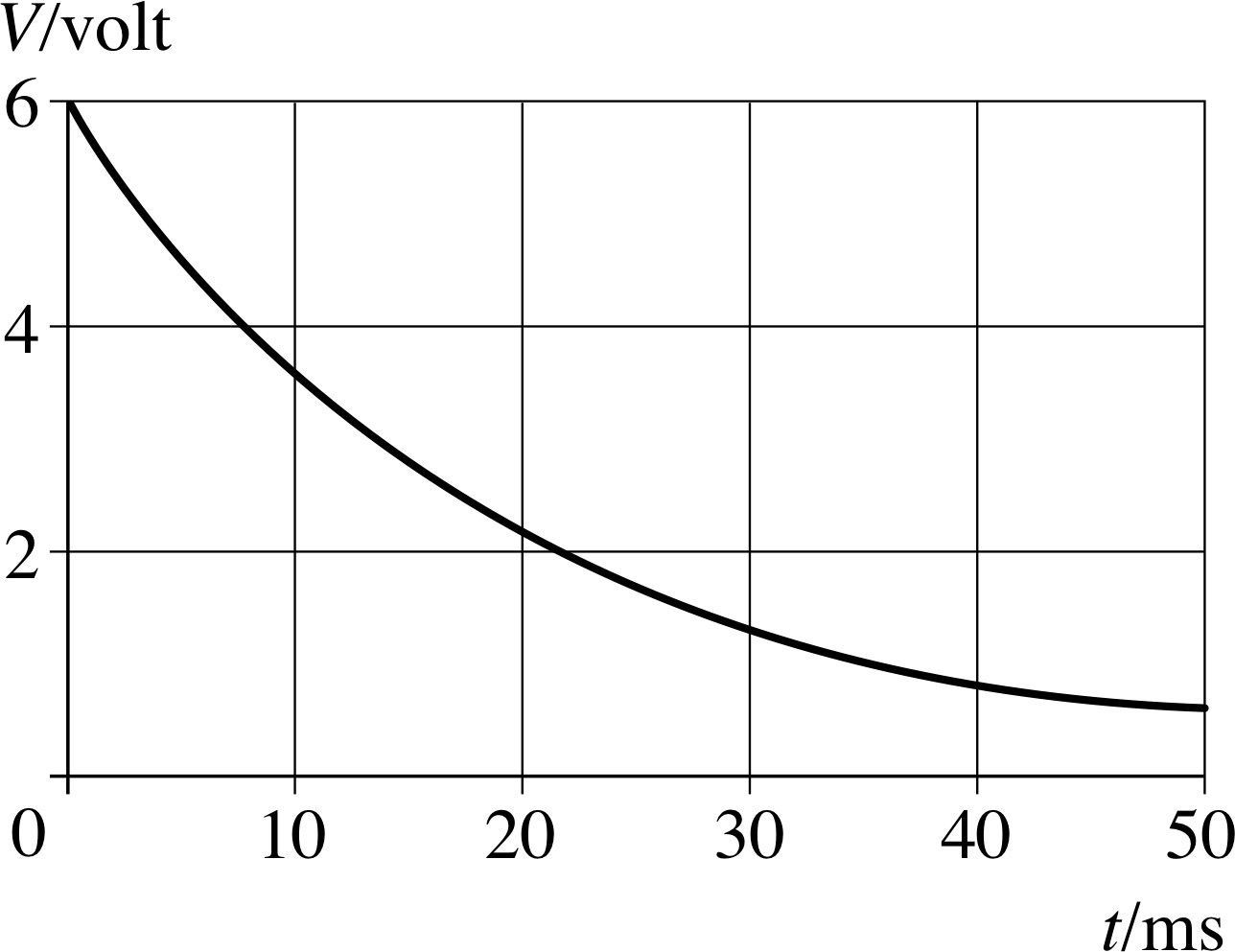
Figure 9 Discharge curve for a capacitor. See Question T6.
Question T6
Figure 9 shows the voltage across a capacitor discharging through a 2 kΩ resistor. Use the graph to find the time constant for the discharge and hence deduce the value of C. What are the initial 4 charge and current q0 and I0? Sketch graphs to show how q and I vary during the first 50 ms of the discharge.
Answer T6
V0 = 6.0 V, and so V0/e ≈ 2.2 V. From Figure 9, V falls from 6.0 V to 2.2 V in 20 ms, therefore τC = 20 ms. (Notice that after a further 20 ms V has fallen by a further factor of e to 0.8 V.)
τC = RC
soC = τC/R = 20 × 10−3 s/(2 × 103 Ω) = 1 × 10⁻⁵ F = 10 μF
Initial charge
q0 = CV0 = 60 μC
Initial current
I0 = V0/R = 6.0 V/ (2 × 10³ Ω) = 3 × 10⁻³ A = 3 mA
The graphs of q and I are identical to Figure 9 apart from the labels on the vertical axis: q starts at 60 μC and takes 20 ms to fall to q0/e = 22 μC, and a further 20 ms to fall by a further factor of e to 8 μC. I starts at 3 mA and takes 20 ms to fall to I0/e = 1.1 mA and then to 0.4 mA after a further 20 ms.
Question T7
How would Figure 9 and your answers to Question T6 be changed if (a) the same capacitor were discharged through a 4 kΩ resistor (b) a capacitor of twice the capacitance were charged from the same battery and discharged through the 2 kΩ resistor?
Answer T7
In both cases, V0 is unchanged at 6.0 V, and the time constant is doubled to 40 ms. Figure 9 would therefore be shallower, with V taking 40 ms to fall from 6.0 V to 2.2 V. All the graphs would have this new time constant, i.e. q and I would also take 40 ms to fall by a factor of e.
In (a), the initial charge q0 is unchanged because C and V0are unchanged, but I0 is halved:
I0 = V0/R = 6.0 V/4 × 103 Ω = 1.5 mA
In (b) the initial current would be unchanged at 3 mA because V0 and
R are unchanged, but the initial charge q0 would be doubled:
q0 = CV0 = 20 μF × 6.0 V = 120 μC
3 Batteries
We have seen how a charged capacitor acts as a short–lived source of potential difference and produces a transient current while discharging. Now we turn our attention to sources of steady direct current.
3.1 Cells, batteries and voltage
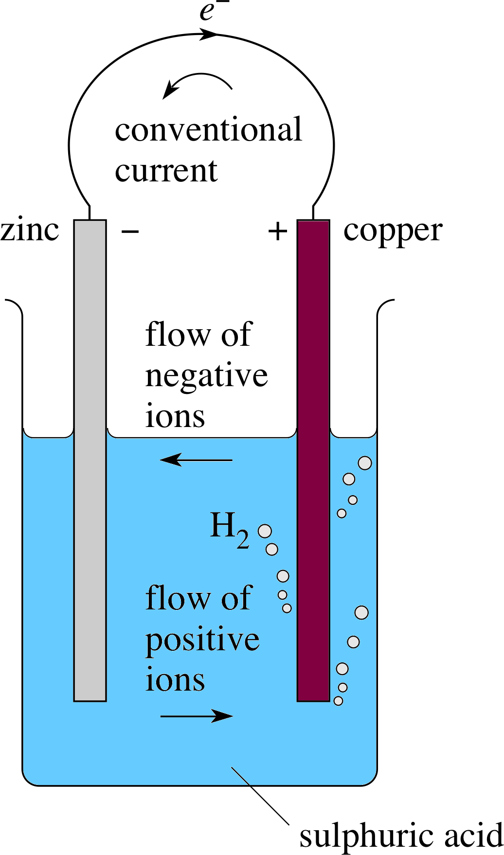
Figure 10 A simple cell.
We will draw a distinction between a single cell and a collection of cells which makes up a battery. This probably seems rather pedantic but you will see later that it is a useful idea. So we will start with a simple cell.
The simplest cells are produced when two different metals are dipped into an electrolyte which is a conducting ionic solution such as a dilute acid. You may have seen electronic clocks which are powered by having two metal rods stuck into a lemon or even a potato where the juice forms the electrolyte. You may even have noticed a rather strange taste in your mouth if you have inadvertently chewed aluminium foil and it has come into contact with the fillings in your teeth. Both of these are forms of simple cell in which a chemical reaction takes place to produce a flow of charged particles which is the current.
For the simple cell in Figure 10 we obtain a change in energy from chemical potential energy to electrical energy. We would normally expect a metal placed into an acid to react to produce hydrogen gas but, in this case, when the two electrodes are joined together in a circuit a difference in the electric potentials of the two metals causes charge to flow between them.
In the simple cell in Figure 10 hydrogen is produced at the surface of the copper plate coming off as bubbles (which can cling to the surface and reduce the area in contact with the electrolyte). While this is happening, zinc is being dissolved from the other plate so that zinc ions (Zn2+) pass into solution leaving the zinc rod negatively charged. The copper rod becomes positively charged and so is able to accept electrons flowing through the wire from the zinc plate. The following reactions take place:
At the negative terminal (zinc): Zn → Zn2+ + 2e−
(one zinc atom produces one zinc ion and two electrons)
In the electrolyte: H2SO4 + 2H2O → 2H3O+ + SO42− i
(sulphuric acid in water produces hydronium ions and sulphate ions)
At the positive terminal (copper): 2H O+ + 2e− → 2H2O + H2 i
(two hydronium ions plus two electrons produce two water molecules plus one hydrogen molecule).
In the metal wire there is a flow of electrons and in the electrolyte a flow of ions – positive ions move towards the copper and negative ions flow towards the zinc – in other words, there is a direct current throughout the circuit. We say that the conventional current direction is that of the (real or apparent) movement of positive charge, i.e. in the wire the current flows from the positive terminal to the negative terminal. This means that electrons (negatively charged) flow in the opposite direction to the conventional current. i
The cell can drive current for as long as the chemical reactions take place. When they stop (for example, because one of the electrodes has entirely dissolved into the electrolyte) we would probably say colloquially that it had ‘gone flat’ or that it had ‘discharged’.
The cell in Figure 10 is just one example of a general rule:
any two different metals dipping into an electrolyte produce an electric cell.
| Element | Chemical symbol |
Electrode potential/V |
|---|---|---|
| potassium | K | −2.93 |
| sodium | Na | −2.71 |
| magnesium | Mg | −2.37 |
| aluminium | Al | −1.66 |
| zinc | Zn | −0.76 |
| iron | Fe | −0.45 |
| tin | Sn | −0.14 |
| lead | Pb | −0.12 |
| hydrogen | H | 0.00 |
| copper | Cu | +0.34 |
| silver | Ag | +0.80 |
The voltage of the cell depends on the metals used, as does the cell’s polarity (i.e. which metal forms the positive terminal and which the negative). Table 2 shows part of the electrochemical series – a listing of elements according to their behaviour in cells. i If you make a cell with any two metals you find that:
- the element nearer the top of Table 2 forms the negative terminal of the cell;
- the further apart the metals are in the series, the greater the cell voltage;
- the cell voltage depends only on the metals used, and not on the electrolyte.
Note This is for an ideal cell. In practice, the cell voltage may be affected by a variety of other factors as discussed in Subsection 3.2.
Notice that zinc is above copper in Table 2 so, as in Figure 10, it forms the negative terminal in a cell made with copper and zinc.
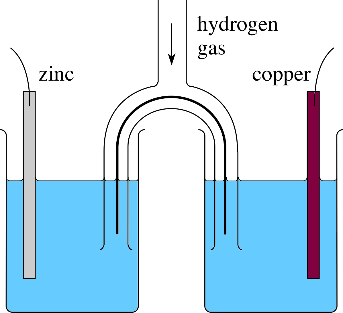
Figure 11 Two cells in series, with a common hydrogen electrode. (The hydrogen gas is at a pressure of 11atm.) A wire connects the two cells.
Figure 11 shows two cells joined in series, with a hydrogen electrode making the positive terminal of one cell and the negative terminal of the other. This arrangement is equivalent to a single cell with zinc and copper electrodes. The net voltage of the two cells in series is the sum of the two separate voltages, so the voltage of the equivalent Zn–Cu cell is the sum of the Zn–H and the H–Cu voltages. A hydrogen–zinc cell has a voltage of 0.76 V (with H being the positive terminal) and a hydrogen–copper cell has 0.34 V (with H being the negative terminal) so a zinc–copper cell will have a voltage of 0.76 V + 0.34 V = 1.10 V. There is nothing special about zinc, copper and hydrogen – a similar argument applies to any two cells with a common electrode. The electrode potential of a metal is defined as the cell voltage obtained when you pair the metal with hydrogen, and it allows you to calculate the voltage of a cell made with any two metals. The sign of the electrode potential takes account of the fact that hydrogen will sometimes be the positive electrode and sometimes the negative. To find the cell voltage, you therefore have to subtract one electrode potential from the other, e.g. for zinc−copper the voltage is 0.34 V − (−0.76 V) = 1.10 V.
Note Hydrogen is used as the ‘standard’ electrode because it gives reliable experimental results. The same argument would apply if any metal were used in place of hydrogen, but the values tabulated in Table 2 would be different.
Question T8
If a cell is made using iron and copper for the electrodes, which metal will form the positive terminal? What will be the cell voltage? What would be the voltage of an iron–zinc cell, and which metal would be the positive terminal?
| Element | Chemical symbol |
Electrode potential/V |
|---|---|---|
| potassium | K | −2.93 |
| sodium | Na | −2.71 |
| magnesium | Mg | −2.37 |
| aluminium | Al | −1.66 |
| zinc | Zn | −0.76 |
| iron | Fe | −0.45 |
| tin | Sn | −0.14 |
| lead | Pb | −0.12 |
| hydrogen | H | 0.00 |
| copper | Cu | +0.34 |
| silver | Ag | +0.80 |
Answer T8
Since copper is placed below iron in the electrochemical series this will be the positive terminal. From Table 2, the cell voltage is 0.34 V − (−0.45 V) = 0.79V.
The voltage of an iron–zinc cell would be −0.45 V − (−0.76 V) = 0.31 V, with iron the positive terminal.
3.2 Factors affecting the performance of cells
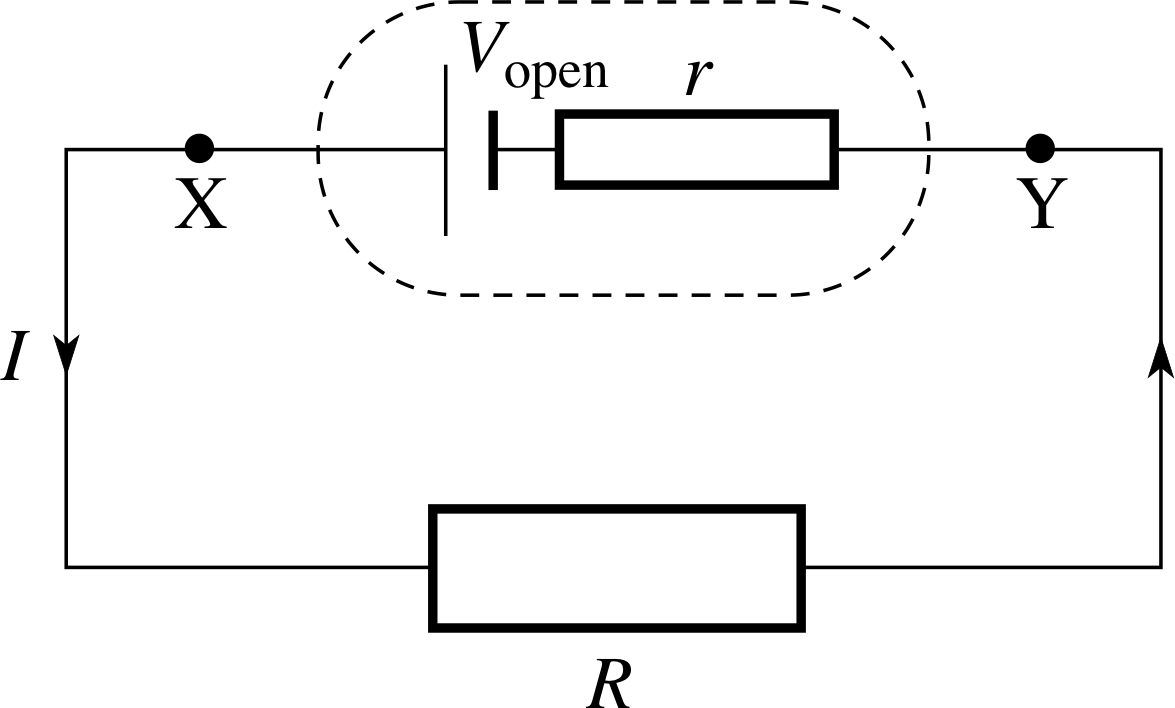
Figure 12 A battery of open circuit voltage Vopen and internal resistance r connected to a resistance R.
Figure 10 A simple cell.
In Subsection 3.1 we talked rather loosely of ‘the voltage’ of a cell. In practice, the potential difference between the terminals of a cell depends on the external circuit, and is a maximum when there is no current. This maximum voltage is the open circuit voltage of the cell, and this is what you calculate when you use the electrode potentials in Table 2. The cell open circuit voltage can be measured with an oscilloscope or with a digital voltmeter because these devices have very high resistance (effectively infinite for most practical purposes), and so a very small current flows (effectively zero).
When a cell drives a current, the potential difference between its terminals drops, due to the cell having an internal resistance which is essentially the resistance of the electrolyte and the electrodes. Figure 12 shows a cell with internal resistance r connected to an external resistor R. The internal resistance is drawn separately, but remember that it is an integral part of the cell, so cannot be removed. The open circuit voltage of the cell Vopen, drives the current through the two resistors r and R, and so the current in the circuit is
$I = \dfrac{V_{\rm open}}{R+r}$(21)
The potential difference V between the terminals X and Y is the same as that across the external resistor, i.e. IR. Rearranging Equation 21 therefore shows that the voltage between the cell terminals is given by
V = Vopen − Ir(22)
So, if a cell has a large internal resistance, there can be quite a drop in terminal potential difference when it is connected in a circuit. i
Apart from internal resistance, there are other factors affecting the performance of cells. In the zinc–copper cell of Figure 10, the zinc plate is eaten away (as the zinc ions go into solution), and the hydrogen produced at the copper electrode sticks to that electrode, reducing its effective area. This local action results in a loss of efficiency of the cell. More significant is the effect of (electrical) polarization_in_a_cellpolarization. Like internal resistance, this is apparent as soon as there is a current. It causes the concentration of ions around both electrodes to change and acts to reduce the open circuit voltage of the cell which may even fall to half its unpolarized value.
Question T9
A cell is connected to a voltmeter of very high resistance, and produces a reading of 1.5 V. When a resistance of 2.5 Ω is connected in parallel with the meter, the reading falls to 1.25 V. Calculate the current in the external resistor and the internal resistance of the cell.
Answer T9
The cell open circuit voltage Vopen = 1.5 V. The potential difference across the external resistor is V = 1.25 V and so I = V/R = 1.25 V/2.5 Ω = 0.5 A
From Equation 22,
V = Vopen − Ir(Eqn 22)
Ir = Vopen − V = 0.25 V, hence internal resistance r = 0.25 V/0.5 A = 0.5 Ω.
3.3 The lead–acid accumulator and the Leclanché dry cell
So far, we have dealt with simple cells of two metals in a solution. We end this section with a look at two slightly more complicated types of cell which you may well have seen: the lead–acid accumulator which is found in most cars and the Leclanché dry cell which is the sort you put in a torch or portable radio. There is an obvious difference between these: an accumulator can be charged and discharged many times but the dry cell can only be used once and is then disposed of. The accumulator is an example of a storage cell because the chemical reaction which takes place inside it is truly reversible.
The lead–acid accumulator
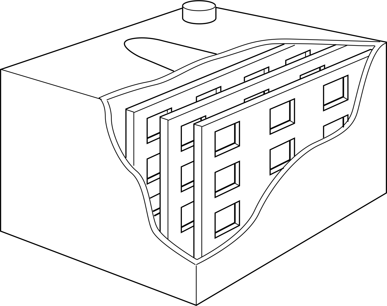
Figure 13 A lead–acid accumulator.
Figure 13 illustrates a battery made from several lead–acid accumulator cells. The electrodes are made from a lead compound pressed into a grid made from an alloy of lead and antimony. The electrodes are manufactured in this way in order to increase their surface area so that they work more effectively. The electrolyte is a strong sulphuric acid solution.
The cells can be ‘charged’ by connecting them to a d.c. supply. As a result, one plate becomes covered in lead oxide (PbO2) whilst the other remains as lead.
The initial voltage of each cell is a little above 2.0 V but this falls to 2.0 V and stays there until the cell is almost fully discharged. A lead–acid accumulator cell has a low internal resistance (about 0.1 Ω). A 12 V car battery has six of these cells connected together in series. While discharging, the negative plate (the lead) and the positive plate (the lead oxide) are both converted into lead sulphate (PbSO4) as the sulphate (SO42−) ions are removed from the solution.
In order to ensure that a car battery is fully charged at all times, it is constantly charged by the alternator while the engine is running. However, once the engine is switched off, it will soon discharge if current is allowed to flow. This is obvious to anyone who has left their car lights on. Some cars will detect this and limit the current to the head lamps.
Even though it can be recharged, a car battery will eventually deteriorate. Each time the battery is charged, oxygen and hydrogen are produced at the electrodes – you can sometimes hear a battery fizzing gently if it has been left to charge overnight – this means that as time goes by water is lost from the electrolyte. This loss of water and the removal of sulphate ions from solution means that the relative density of the electrolyte will change. A useful way of checking the state of a battery is to use a special bulb hydrometer to measure the density of the electrolyte which should be about 1.21 times the density of water. The life of a car battery can be prolonged by adding distilled water at regular intervals. Ultimately the plates will begin to fail mechanically and it is this which spells the end of most car batteries.
The Leclanché dry cell
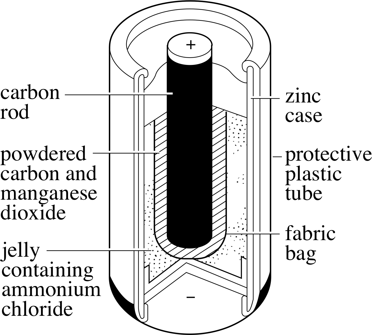
Figure 14 A Leclanché dry cell.
Figure 14 shows a Leclanché dry cell, commonly used in torches. i The positive terminal is carbon, and the outer zinc casing forms the negative electrode. The cell voltage is close to 1.5 V. The ammonium chloride electrolyte is absorbed in a moist jelly or paste – so the cell is not strictly ‘dry’, but it does avoid the spillage problems of liquid electrolytes.
When the cell is working, Zn2+ ions are produced at the negative terminal, releasing electrons that flow around the external circuit. At the positive terminal, electrons neutralize HO+ ions to produce hydrogen gas and water. The manganese dioxide (MnO2) around the carbon removes the hydrogen gas:
2MnO2 + H2 → Mn2O3 + H2O
The cell goes ‘flat’ when either the electrolyte dries out or the manganese dioxide is all used up. The reaction is not reversible so the cell cannot be recharged.
A Leclanché dry cell has an internal resistance of typically around 1 Ω. In practice the high internal resistance is not necessarily a disadvantage: since it can only produce currents up to about 1.5 A, a Leclanché dry cell can produce little damage.
Question T10
What would be the disadvantages of using (a) Leclanché dry cells to make a car battery, (b) a lead–acid accumulator in a portable radio?
Answer T10
(a) The battery would soon go ‘flat’ since it cannot be recharged. Its large internal resistance means that it would be unable to supply the large current (typically, many tens of amps) necessary for starting a car.
(b) The sulphuric acid electrolyte would spill easily, causing danger due to corrosion. If a low resistance were connected between the terminals, the small internal resistance would allow the battery to deliver a large current which could cause damage due to heating.
4 Coils in circuits
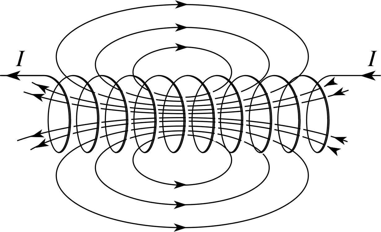
Figure 15 The magnetic field due to a current in a solenoid.
In this section, you will see that the mathematical description of coils in circuits is in some ways similar to that used in Section 2 for capacitors, even though coils and capacitors are quite unlike each other. We begin with a brief review of some magnetic effects of a current in a coil.
4.1 Current and magnetism
| Material | Relative permeability μr |
|---|---|
| air | 1.0005 |
| transformer steel | 5500 |
| high purity iron | 121 600 |
| standard sheet steel | 2000 |
| specialized alloys: | |
| mu-metal | 100 000 |
| supermalloy | 800 000 |
A current in a coil of wire produces a magnetic field i along the axis of the coil, as shown in Figure 15. If the coil is closely wound, and long compared to its width, the field is more-or-less uniform within the coil. (Such a coil is known as a solenoid.)
The strength of the magnetic field depends upon the current, the number of turns per unit length of the solenoid and the magnetic properties of the material in the core of the solenoid. For a long solenoid having N turns in a length l, carrying a current I and wound on a core of relative permeability μr, the magnetic field strength B is given by
$B = \dfrac{\mu_{\rm r\,}\mu_0NI}{l}$(23) i
B is also known as the magnetic flux density. Its SI units are tesla, T, or webers per square metre, Wb m−2. i Table 3 shows a few typical relative permeabilities for materials. The magnetic flux ϕ within each turn of the coil is a measure of the ‘amount of field’ within the coil. For each turn of the coil of cross–sectional area A:
magnetic flux per turn ϕ = BA(24)
✦ What are the SI units of ϕ?
✧ The magnetic flux ϕ has SI units of magnetic field strength × area, i.e. Wb.
When the magnetic flux within a coil changes – either because of changes in an external magnetic field, or because of changes in the magnetic field produced by the current in the coil itself – electromagnetic induction i takes place, i.e. there is an induced voltage produced in the coil.
faradays_lawFaraday’s law of electromagnetic induction states that the magnitude of the induced voltage depends on the rate at which the magnetic flux changes, and the number of turns in the coil. The total magnetic flux linkage Φ is defined as
total magnetic flux linkage Φ = Nϕ(25) i
The magnitude of the induced voltage Vind is related to the rate of change of this flux linkage according to Faraday’s law:
Faraday’s law
magnitude of induced voltage $V_{\rm ind} = \left\lvert\,\dfrac{d{\it\Phi}}{dt}\,\right\rvert$(26)
In addition the polarity of this induced voltage is always such as to oppose the changes causing it. This is known as Lenz’s law. i
When there is a steady direct current in a coil, the flux linkage is not changing so there is no induced voltage. However, when the current is switched on or off, there is a rapid change in flux which induces a voltage between the ends of the coil. The direction of this self induced voltage is such as to ‘try’ to maintain the current in the coil after it is switched off, or to prevent the build up of current when it is switched on, so it is sometimes known as a back voltage.
Equations 23 to 26 can be combined to show that the magnitude of the self induced voltage is given by
$V_{\rm ind} = \dfrac{\mu_{\rm r\,}\mu_0AN^2}{l}\left\lvert\,\dfrac{dI}{dt}\,\right\rvert$(27)
A coil that is designed to produce a large self induced voltage is often known as an induction coil or an inductor.
✦ How would you design a coil to produce a large self induced voltage?
✧ The coil should have many closely–wound turns (large N, small l) on a material of high relative permeability μr, such as iron.
Equation 27 can be written more compactly as
$V_{\rm ind} = L\,\left\lvert\,\dfrac{dI}{dt}\,\right\rvert$(28)
where L is the coefficient of self inductance (often just called the inductance) and is therefore given by
$L = \dfrac{\mu_{\rm r\,}\mu_0AN^2}{l}$(29)
The SI unit of self inductance is the henry, H.
Question T11
Satisfy yourself that 1 H = 1 V s A−1 and that the units (V s A−1) and (Wb A−1) and are equivalent.
Answer T11
From Equation 28, self–inductance L has the units of Vind/(dI/dt) = V/(A s−1) = V s A−1, so 1 H = 1 V s A−1.
From Equation 26,
magnitude of induced voltage $V_{\rm ind} = \left\lvert\,\dfrac{d{\it\Phi}}{dt}\,\right\rvert$(Eqn 26)
1 V = 1 Wb s−1, and so 1 V s A−2 = 1 Wb A−2.
Question T12
A coil of self inductance 6 H carries a current growing at a rate of 0.2 A s−1. Calculate the voltage induced in the coil. i
Answer T12
Using Equation 28,
$V_{\rm ind} = L\,\left\lvert\,\dfrac{dI}{dt}\,\right\rvert$(Eqn 28)
and 1 H = 1 V s A−1,
Vind = 6 V s A−1 × 0.2 A s−1 = 1.2 V
Question T13
An air–cored solenoid has 500 turns. It has a length of 10 cm and a diameter of 1.5 cm. Calculate its self inductance. i
Answer T13
Using Equation 29, (with μr ≈ 1)
$L = \dfrac{\mu_{\rm r\,}\mu_0AN^2}{l}$(Eqn 29)
$L = \dfrac{\mu_0AN^2}{l} = \rm \dfrac{4\pi\times10^{-7}\,H\,m^{-1}\times500^2\times\pi\times(0.0075\,m)^2}{0.1\,m} = \rm 5.6\times10^{-4}\,H = 560\,\text{μ}H$
4.2 Transients in inductive circuits
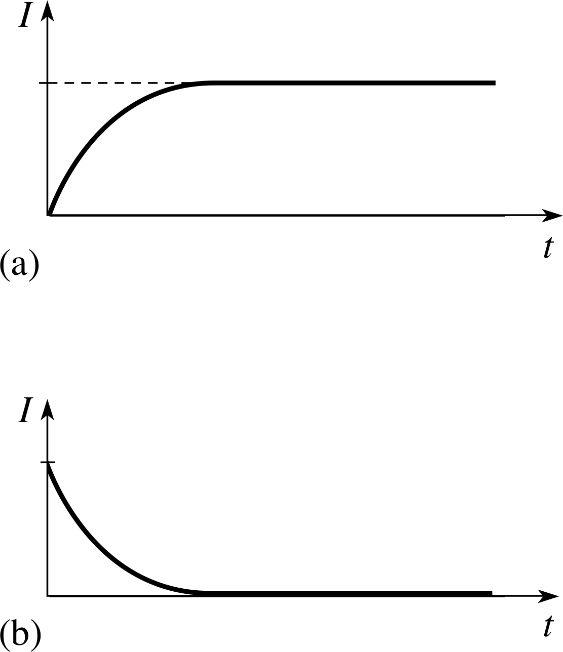
Figure 17 Current in the circuit of Figure 16 when (a) the switch is moved to A, and (b) the switch is moved to B.
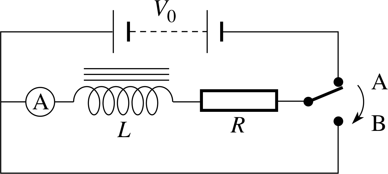
Figure 16 An inductor in series with a resistor and a d.c. power supply. i
Figure 16 shows an inductor in series with a resistor and a d.c. power supply. With the switch at A, there is a direct current in the resistor and inductor. When the switch is first closed and the current begins to rise there is a voltage induced in the inductor that tries to prevent the magnetic flux building up. In other words, the induced voltage tries to prevent the current building up, so there is a delay in the current reaching its final steady value as shown in Figure 17a. i If the power supply has voltage V0, then the steady current is I0 = V0/R. Once the current reaches a steady value, there is no induced voltage, so there is effectively just a d.c. supply and a resistor in the circuit. This is another example of a transient current, such as we met in Subsection 2.4.
When the switch in Figure 16 is moved to B and the current begins to fall there is again an induced voltage in the coil which now tries to maintain the magnetic flux within the coil by maintaining the previous current. As shown in Figure 17b, there is now a delay in the current falling to zero. This transient current can be described in a very similar way to that in a capacitor circuit discussed in Subsection 2.4, even though the two arise in quite different ways.
When the steady current is switched off by moving the switch to B, the voltage Vind induced in the coil provides a potential difference across the resistor such that Vind = IR. If we remember Lenz’s law the change in the current produces an induced voltage which opposes this change.
We can incorporate this polarity into Equation 2,
$V_{\rm ind} = L\,\left\lvert\,\dfrac{dI}{dt}\,\right\rvert$(Eqn 28)
to find
$IR = -L\dfrac{dI}{dt}$(30)
✦ Equation 30 describes an exponential decay. Write down an equation that describes how I changes with time after the switch is moved to B. [Hint: Look back at Equations 16 and 17.]
$\dfrac{dq}{dt} = -\dfrac{q}{RC} = -\dfrac{1}{RC}q$(Eqn 16)
q (t) = q0 e−t/RC(Eqn 17)
✧ I at time t is given by:
I (t) = I0 e−Rt/L(31)
As was the case in the capacitive circuit, this transient current approaches zero gradually, so it is useful to define
the inductive time constant τL is the time taken for the current I to fall to 1/e of its initial value:
$\tau_L = \dfrac LR$(32)
Notice that L/R has appropriate units. Its SI units are H Ω−1. 1 H = 1 V s A−1 (see Question T11) and, since R = V/I, 1 Ω = 1 V A−1 so 1 H Ω−1 = 1 s. When the switch is at position A, the induced voltage opposes the battery and so the net potential difference across the resistor is V0 − LdI/dt. It is this potential difference that drives the current in the resistor, so we can therefore say that
$IR = V_0 - L\dfrac{dI}{dt}$(33)
This leads to an expression for the growing current:
$I = I_0\left(1 - {\rm e}^{-Rt/L}\right)$(34) i
Question T14
Which of the following quantities decay exponentially when the power supply in an inductive circuit is disconnected?
Magnetic field strength B in the coil;
magnetic flux ϕ in the coil;
self inductance L;
power supply voltage V0;
potential difference V across the resistor.
For those that do decay exponentially, what is the time constant for each of their decays? Sketch graphs to show the induced voltage in a coil as the current changes as shown in Figure 17.
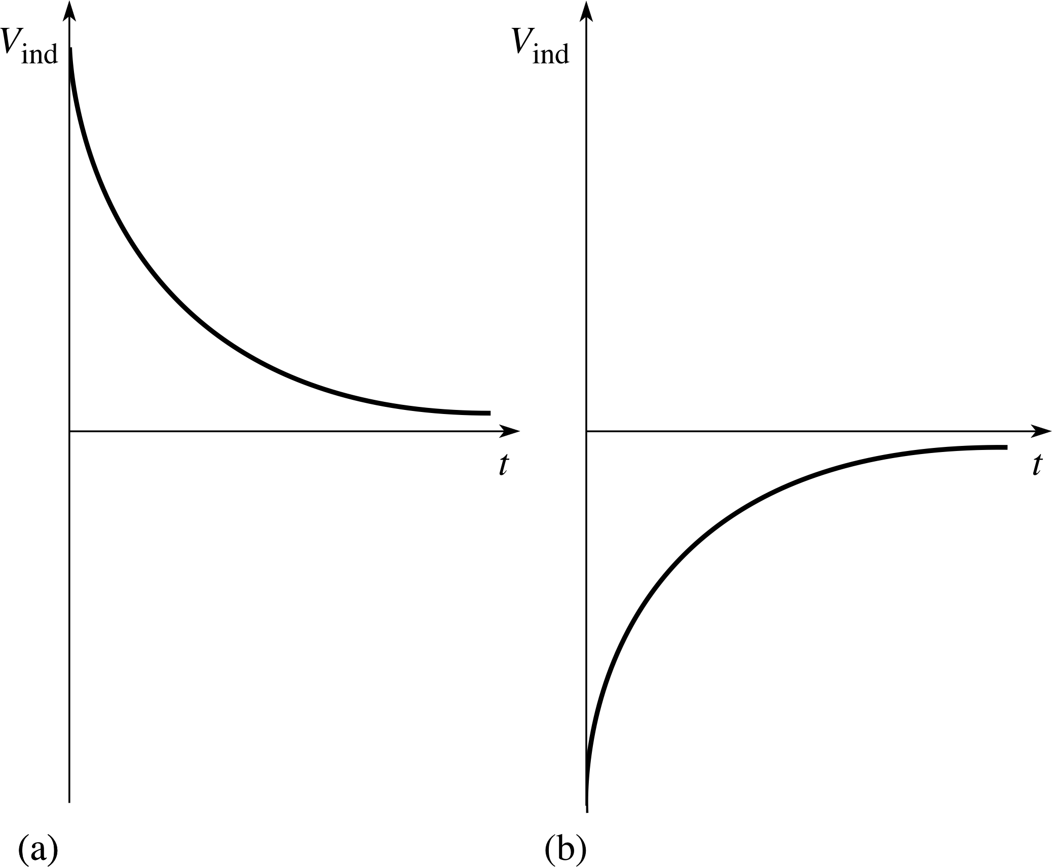
Figure 19 See Answer T14.
Answer T14
L and V0 are both constants for a given circuit, so do not decay. All the other quantities listed are directly proportional to the current I:
so from Equation 23,
$B = \dfrac{\mu_{\rm r\,}\mu_0NI}{l}$(Eqn 23)
B ∝ I
and from Equation 24,
magnetic flux per turn ϕ = BA(Eqn 24)
ϕ ∝ B
and so ϕ ∝ I, V = IR and so V ∝ I.
For each of these, an equation describing the decay can be produced by multiplying Equation 31,
I (t) = I0 e−Rt/L(Eqn 31)
by an appropriate constant factor: for example, V = IR = I0Re−rt/L.
The exponent −Rt/L is the same in each case, so each decay has the same time constant τC = L/R.
Figure 19 shows the induced voltage (including polarity) across a coil (b) as the current builds up and (a) as the current dies away.
Question T15
Explain physically why the inductive time constant is (a) directly proportional to L, and (b) inversely proportional to R.
Answer T15
(a) The larger the value of L, the greater the induced voltage opposing a given change of current, so the longer it takes for the current to reach a steady value.
(b) If the resistance is large the steady current, and hence the steady magnetic field in the coil, are small. Switching the current off (or on) leads to a small change in flux linkage, which in turn induces only a small voltage to oppose the change, and so the current can change relatively rapidly.
4.3 Stored magnetic energy
When the current in an inductor grows and decays, energy is being stored in the coil as the field is established and then used to drive current after the power supply has been disconnected. It is this stored energy which we will now look at.
The rate at which the battery supplies energy to the circuit is given by V0I. If we rearrange Equation 33,
$IR = V_0 - L\dfrac{dI}{dt}$(Eqn 33)
to make V0 the subject, and multiply throughout by I, we obtain an expression that describes what happens to this energy when the power supply is connected:
$V_0I = LI\dfrac{dI}{dt} + I^2R$(35)
The term I 2R describes the rate at which energy is being dissipated as heat in the resistor, and so the term LIdI/dt must describe the rate at which magnetic energy Emag is being stored as the magnetic field is set up, i.e.
$\dfrac{dE_{\rm mag}}{dt} = LI\dfrac{dI}{dt}$(36)
The energy ∆Emag stored during a short time interval ∆t is given by
$E_{\rm mag} = \left(\dfrac{dE_{\rm mag}}{dt}\right)\Delta t = LI\dfrac{dI}{dt}\Delta t$(37)
So, the total energy stored is the sum of all these small energies,
$\displaystyle E_{\rm mag} = \sum\Delta E_{\rm mag} = \sum LI\dfrac{dI}{dt}\Delta t$
If ∆t is very small, we can then replace the summation by an integral, and so
$\displaystyle E_{\rm mag} = \int_0^{I_0}LI\dfrac{dI}{dt}\,dt = \int_0^{I_0}LI\,dI$(38)
and hence $E_{\rm mag} = \dfrac12 LI_0^2$(39)
where I0 is the final value of the current that flows in the circuit.
Compare Equation 39 with Equation 10,
$E_{\rm el} = \dfrac12 \dfrac{q_0^2}{C} = \dfrac12q_0V_0 = \dfrac12CV_0^2$(Eqn 10)
and notice that we again have a similarity between the descriptions of an inductive and a capacitive circuit. In Subsection 2.3 we attributed the stored energy to an electric field and found an expression for the energy density in the field. Here, the energy is due to the magnetic field, and it can be shown that (see Question T17)
a magnetic field of magnitude B in a medium of relative permeability μr has an energy density of B2/(2μrμ0).
Notice the similarity between this expression and that for the energy density in an electric field. The only difference is that permittivity appears on the top line in the equation for electric field energy density and permeability appears on the bottom line in the equation for magnetic field energy density. Indeed, one of the main messages of Sections 2 and 4 of this module is that there are many similarities between the mathematical descriptions of capacitors and electric fields, and of inductors and magnetic fields.
Question T16
A coil of self inductance 5 mH and resistance 10 Ω is connected to a 6 V supply. Calculate the energy stored when the magnetic field is fully established.
Answer T16
When the field is fully established, from Equation 39,
$E_{\rm mag} = \dfrac12 LI_0^2$(Eqn 39)
I0 = V0/R = 6 V/10 Ω = 0.6 A.
So,
energy stored = $\dfrac12 LI_0^2 = \rm \dfrac{5\times10^{-3}\,H\times0.6\,A\times0.6\,A}{2} = 9\times10^{-4}\,J$
Question T17
A current I in a solenoid of length l and area A, and self inductance L, produces a uniform magnetic field of strength B throughout the space enclosed by the coil. Show that the energy density in the magnetic field is B2/(2μrμ0).
Answer T17
The energy density is the energy per unit volume. The coil encloses a volume lA so, from Equation 39,
$E_{\rm mag} = \dfrac12 LI_0^2$(Eqn 39)
the energy density is given by $\dfrac{E_{\rm mag}}{lA} = \dfrac{LI^2}{2lA}$
but,$L = \dfrac{\mu_{\rm r\,}\mu_0AN^2}{l}$(Eqn 29)
and, from Equation 23,
$B = \dfrac{\mu_{\rm r\,}\mu_0NI}{l}$(Eqn 23)
$I = \dfrac{lB}{\mu_{\rm r\,}\mu_0N}$
Substituting for L and I gives
$\dfrac{E_{\rm mag}}{lA} = \dfrac{\mu_{\rm r\,}\mu_0N^2A}{l}\times\dfrac{l^2B^2}{\mu^2_{\rm r\,}\mu_0^2N^2}\times\dfrac{1}{2lA} = \dfrac{B^2}{2\mu_{\rm r\,}\mu_0}$
5 Closing items
5.1 Module summary
- 1
-
A capacitor is a device for storing charge. If a charge +q is stored on one plate of a capacitor, there is a charge −q on the other plate.
- 2
-
The charge stored is related to the potential difference across the capacitor
q = CV(Eqn 1)
where C is the capacitance. The SI unit of capacitance is the farad (F). 1 F = 1 C V−1.
- 3
-
For two parallel plates separated by a distance d and with an area of overlap A,
C = Aε/d(Eqn 2)
where ε is the permittivity of the material between the plates.
- 4
-
When capacitors are connected in parallel
C = C1+ C2 + C3(Eqn 4)
- 5
-
When capacitors are connected in series
$\dfrac1C = \dfrac{1}{C_1} + \dfrac{1}{C_2} + \dfrac{1}{C_3}$(Eqn 5)
- 6
-
An inductor is a coil designed to produced a large self induced voltage when the current in it changes.
- 7
-
The magnitude of the induced voltage Vind is related to the rate of change of current
$V_{\rm ind} = L\,\left\lvert\,\dfrac{dI}{dt}\,\right\rvert$(Eqn 28)
L is the coefficient of self inductance. The SI unit of self inductance is the henry (H), 1 H = 1 V s A−1.
- 8
-
For a solenoid of cross–sectional area A, with N turns in a length l, wound on a material of relative permeability μr
$L = \dfrac{\mu_{\rm r\,}\mu_0AN^2}{l}$(Eqn 29)
- 9
-
A charged capacitor stores electrical energy
$E_{\rm el} = \frac12CV_0^2$(Eqn 10)
- 10
-
The energy density in an electric field of magnitude E (such as that between the plates of a charged capacitor) is εE, where ε = ε0εr.
- 11
-
An inductor in which there is a steady current stores magnetic energy
$E_{\rm mag} = \frac12 LI_0^2$(Eqn 39)
- 12
-
The energy density in a magnetic field of magnitude B (such as that within a current–carrying solenoid) is $\frac12 B^2\mu$, where μ = μ0μr.
- 13
-
In a d.c. circuit with a capacitor and a resistor, charge flows for a short time while the capacitor is charging and discharging, producing a transient current.
- 14
-
In a d.c. circuit consisting of a capacitor C in series with a resistor R, the current changes exponentially while the capacitor is discharging and charging, as does the potential difference across the capacitor and the charge stored on it. For example, during discharge
q (t) = q0 e−t/RC(Eqn 17)
- 15
-
When a capacitor discharges through a resistor, the capacitive time constant τC = RC is the time for the current, voltage and stored charge to fall by a factor e.
- 16
-
In a d.c. circuit consisting of an inductor L in series with a resistor R, the current changes exponentially when the power supply is disconnected or connected, as does the induced voltage across the inductor and the magnetic flux within it. For example, when the power supply is disconnected
I (t) = I0 e−R t/L(Eqn 31)
- 17
-
When the current falls after the power supply is disconnected from an inductor, the inductive time constant τL = L/R is the time for the current, induced voltage and magnetic flux to fall by a factor e.
- 18
-
A simple electric cell consists of any two different metal electrodes dipping into an electrolyte. Chemical reactions between the electrodes and the electrolyte give rise to a potential difference between the electrodes, and the electrode made of whichever metal has the higher electrode potential forms the positive terminal.
- 19
-
The open circuit voltage of an ideal cell is found by subtracting the electrode potentials of the electrodes one from another. The further apart the metals are in the electrochemical series, the greater the open circuit voltage.
- 20
-
Lead–acid accumulators are widely used because they are rechargeable and have low internal resistance. Leclanché dry cells have a higher internal resistance and are a safe transportable power source. i
- 21
-
The internal resistance of any electric cell or battery is due to the electrical resistance of the materials from which it is made. When a cell is connected in a circuit of finite resistance, its internal resistance causes the potential difference between its terminals to fall.
- 22
-
Polarization and local action around the electrodes also cause a drop in the voltage between the terminals of a cell and may limit its usefulness.
5.2 Achievements
Having completed this module, you should be able to:
- A1
-
Define the terms that are emboldened and flagged in the margins of the module.
- A2
-
Describe the structure of simple capacitors and relate this to their capacitance.
- A3
-
Calculate values of capacitance for series and parallel combinations.
- A4
-
Sketch and interpret graphs showing the growth and decay of transient currents and related quantities in capacitive and inductive circuits.
- A5
-
Establish and use the mathematical description of transient currents and voltages in capacitors and inductors.
- A6
-
Calculate the capacitive time constant and the inductive time constant of simple circuits.
- A7
-
Calculate the energy stored in the electric and magnetic fields within capacitors and inductors.
- A8
-
Describe and explain the structure of simple electric cells and the Leclanché dry cell and the lead–acid accumulator.
- A9
-
Use the electrochemical series and electrode potentials to determine the polarity and open circuit voltage of a simple cell.
- A10
-
Describe the origin of internal resistance and other factors that affect the performance of cells and batteries.
Study comment You may now wish to take the Exit test for this module which tests these Achievements. If you prefer to study the module further before taking this test then return to the topModule contents to review some of the topics.
5.3 Exit test
Study comment Having completed this module, you should be able to answer the following questions each of which tests one or more of the Achievements.
Question E1 (A2)
Describe briefly the structure of a parallel–plate capacitor and explain how the capacitance depends upon its dimensions and the materials from which it is made.
Answer E1
A capacitor may be made from two parallel metal plates separated by a dielectric (non-conducting) material. The capacitance is C = εrε0A/d where A is the area of overlap of the plates, d the plate separation, ε0 the permittivity of free space and εr the relative permittivity (dielectric constant) of the dielectric.
(Reread Subsection 2.1 if you had difficulty with this question.)
Question E2 (A3)
Two capacitors of value 20 μF are connected to a 12 V d.c. supply. Calculate the charge stored when these capacitors are connected, (a) in series, and (b) in parallel.
Answer E2
(a) For capacitors joined in series
$\dfrac1C = \dfrac{1}{C_1} + \dfrac{1}{C_2} = \rm \dfrac{1}{20\text{μ}F} + \dfrac{1}{20\text{μ}F}$
henceC = 10 μF
Using Equation 1, q = CV = 10 μF × 12 V = 120 μC
(b) For capacitors in parallel, (from Equation 4)
C = C1 + C2 = 20 μF + 20 μF = 40 μF
charge stored = 40 μF × 12 V = 480 μC
(Reread Subsections 2.1 and 2.2 if you had difficulty with this question.)
Question E3 (A4 and A6)
On one set of labelled axes, sketch graphs which show the variation in current when the capacitor arrangements described in Question E2 (a) and (b) are discharged through a 1 kΩ resistor.
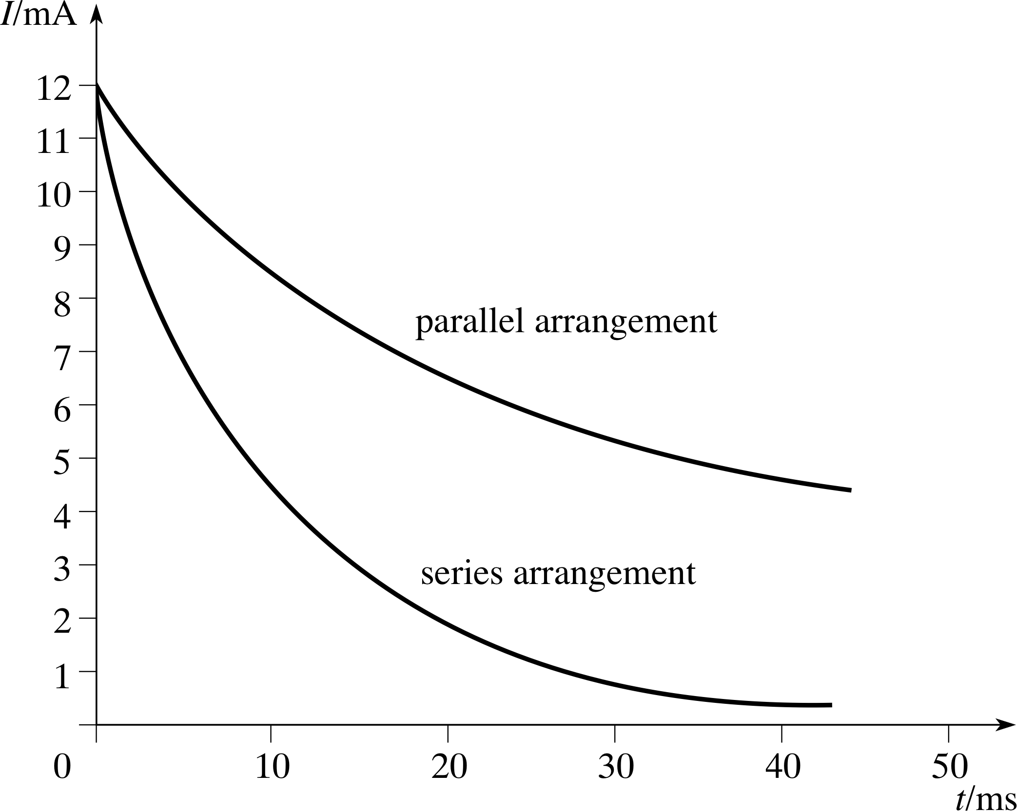
Figure 20 See Answer E3.
Answer E3
See Figure 20. In each case, the initial voltage V0 is 12 V so the initial current is
I0 = V0/R = 12 V/(1 × 103 Ω) = 12 mA and I0/e = 4.4 mA.
For the series arrangement, the time constant is (from Equation 20)
τC = RC = 10 × 10−6 F × 1 × 103 Ω = 10 ms
so the current takes 10 ms to fall to 4.4 mA.
For the parallel arrangement, the capacitance is four times larger so τC = 40 ms and it takes 40 ms for the current to fall to 4.4 mA.
(Reread Subsection 2.4 if you had difficulty with this question.)
Question E4 (A7)
A 200 μF capacitor is connected across a 6 V battery. Calculate the energy stored in the capacitor when it is fully charged.
Answer E4
Using Equation 10,
energy stored = $\dfrac12 CV^2 = \rm \dfrac{2\times10^{-4}\,F\times6\,V\times6\,V}{2} = 3.6\times10{-3}\,J$
(Reread Subsection 2.3 if you had difficulty with this question.)
Question E5 (A5)
The expression $I = \dfrac{V_0}{R}\left(1 - {\rm e}^{-tR/L}\right)$ describes the behaviour of the current I in a circuit.
What is the physical meaning of the symbols V0, R and L in this expression?
What is the significance of the time t = L/R?
What are the values of I when t = 0, when t is very large, and when t = L/R?
Answer E5
V0 is the voltage of a d.c. power supply (e.g. a battery) connected across an inductor and resistor in series. L is the self–inductance of the circuit (a measure of its opposition to changes in current) and R the resistance. L/R is the inductive time constant, i.e. the time taken for the current to fall by a factor of e when the power supply is disconnected.
The expression in the question refers to the build–up of current when the power supply is connected:
when t = 0, e−tR/L = 1 and so I = 0;
when t is very large, e−tR/L ≈ 0 and so I ≈ V0/R;
when t = L/R, I = V0(1 − 1/e)/R, i.e. the current has still to rise by 1/e of its eventual steady value.
(Reread Subsection 4.2 if you had difficulty with this question.)
Question E6 (A8 and A9)
Describe the construction of a simple electric cell. How would you use the electrochemical series and tabulated values of electrode potential to predict the polarity and open circuit voltage of such a cell?
Answer E6
A simple electric cell consists of electrodes made from any two different metals dipping into an electrolyte, i.e. an ionic conducting solution. The metal higher up the electrochemical series forms the negative terminal, and the cell’s open circuit voltage is found by subtracting one electrode potential from the other.
(Reread Subsection 3.1 if you had difficulty with this question.)
Question E7 (A8 and A10)
A 1.5 V Leclanché dry cell is connected to a digital voltmeter in open circuit so that a value of 1.5 V is read on the meter. However, when the dry cell is connected across a resistor of value 100 Ω, the reading on the voltmeter falls to 1.25 V. Using this information calculate the internal resistance of the cell and explain how this internal resistance arises.
Answer E7
Cell open circuit voltage Vopen = 1.5 V, terminal potential difference V = 1.25 V.
From Equations 21 and 22,
$I = \dfrac{V_{\rm open}}{R+r}$(Eqn 21)
V = Vopen − Ir(Eqn 22)
Ir = Vopen − V = 1.5 V − 1.25 V = 0.25 V
$I = \dfrac VR = \rm \dfrac{1.25\,V}{100\,\Omega} = 0.0125\,A (12.5\,mA)$
so$r = \dfrac{V_{\rm open} - V}{I} = \rm \dfrac{0.25\,V}{0.0125\,A} = 20\,\Omega$
Internal resistance is the resistance of the materials from which the cell is made – in this case, a carbon rod surrounded by manganese dioxide and a paste containing the electrolyte.
(Reread Subsections 3.2 and 3.3 if you had difficulty with this question.)
Study comment This is the final Exit test question. When you have completed the Exit test go back and try the Subsection 1.2Fast track questions if you have not already done so.
If you have completed both the Fast track questions and the Exit test, then you have finished the module and may leave it here.
Study comment Having seen the Fast track questions you may feel that it would be wiser to follow the normal route through the module and to proceed directly to the following Ready to study? Subsection.
Alternatively, you may still be sufficiently comfortable with the material covered by the module to proceed directly to the Section 5Closing items.