PHYS 6.4: Optical instruments |
PPLATO @ | |||||
PPLATO / FLAP (Flexible Learning Approach To Physics) |
||||||
|
1 Opening items
1.1 Module introduction
This module begins with a discussion of magnification, aberration and resolution and moves on to show how these concepts are important in the design of a variety of optical instruments, including the eye. Throughout most of the module we treat light as travelling in rays, because geometrical optics is the most useful way to approach optical instruments. The main exception is in the discussion of resolution and angular resolving power, where the wave aspects of light are paramount. There are a number of suggested simple experiments which you may like to try whilst working through the module; these will give you a better ‘feel’ for the phenomena, but they are optional.
Section 2 defines three different measures of magnification – transverse magnification, angular magnification and magnifying power – and describes the appropriate situations in which they can be applied. Practical optical instrument design must successfully limit the effects of the various aberrations present in real lenses and mirrors, including spherical aberration, coma and chromatic aberration. The first two may be reduced by careful design of the refracting or reflecting surfaces whilst the third is minimized for lenses by using achromatic doublets. Section 2 also describes resolution and angular resolving power, as being limited by diffraction, and introduces the Rayleigh criterion of resolution.
Section 3 describes the structure and function of the eye, along with its most common deficiencies of long sight and short sight. Several of the more subtle features of the eye are mentioned, including how its graded index lens reduces spherical aberration, how its resolution is limited and how depth perception is achieved.
Section 4 describes some simple optical instruments, including the magnifying glass and the pinhole camera. This leads, in Section 5, to the photographic camera and a comparison of its function with that of the eye. In this section also is the main discussion of the more important instruments which use more than a single optical component. This discussion includes the compound microscope, the refracting telescope, binoculars, various designs of reflecting telescope and finally the spectrometer.
Study comment Having read the introduction you may feel that you are already familiar with the material covered by this module and that you do not need to study it. If so, try the following Fast track questions. If not, proceed directly to the Subsection 1.3Ready to study? Subsection.
1.2 Fast track questions
Study comment Can you answer the following Fast track questions? If you answer the questions successfully you need only glance through the module before looking at the Subsection 6.1Module summary and the Subsection 6.2Achievements. If you are sure that you can meet each of these achievements, try the Subsection 6.3Exit test. If you have difficulty with only one or two of the questions you should follow the guidance given in the answers and read the relevant parts of the module. However, if you have difficulty with more than two of the Exit questions you are strongly advised to study the whole module.
Question F1
Sketch the ray diagram for the arrangement of lenses in a simple refracting astronomical telescope to show how an image is formed. Explain how the ability of a telescope to resolve small features on the object depends on the size of the telescope’s objective. Why is the eyepiece normally adjusted so that the final image is formed at infinity?
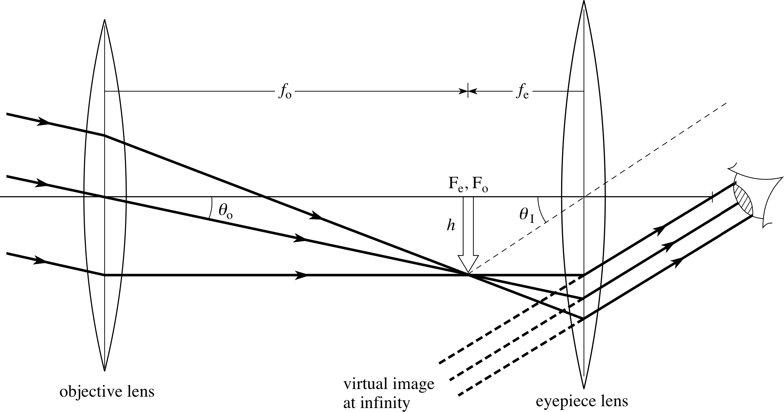
Figure 23 A simple astronomical telescope. The objective has a long focal length whilst that of the eyepiece is much shorter.
Answer F1
The ray diagram for a simple astronomical refracting telescope is shown in Figure 23. The focal points of the objective and the eyepiece are normally made to coincide so that an inverted, magnified image is viewed at infinity. This means that the observer’s eye is fully relaxed and subject to less strain. The angular limit of resolution for a telescope objective of diameter d is 1.22λ/d where λ is the wavelength of the radiation – the larger the objective diameter, the greater the ability to resolve fine detail on the object. You will find a discussion of angular resolving power in Subsection 2.3.
Question F2
With the aid of a diagram, describe what is meant by an achromatic doublet and say how this can be used to correct for lens aberrations.
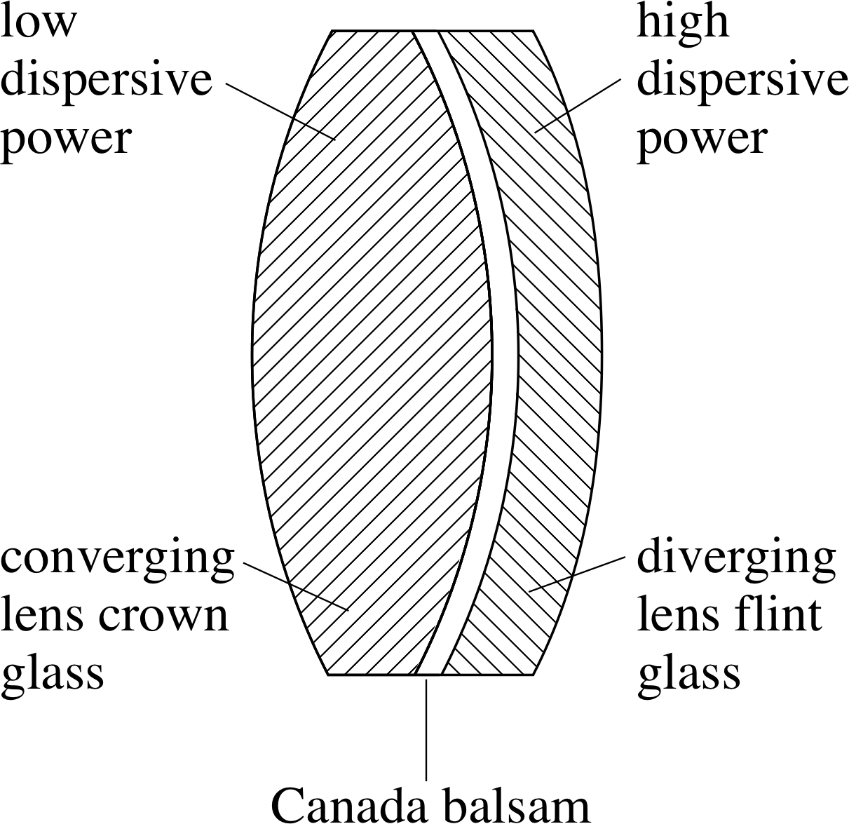
Figure 10 An achromatic doublet.
Answer F2
An achromatic doublet is formed by cementing together two lenses with equal and opposite chromatic aberrations (see Figure 10). One lens is converging and made from crown glass, with a low average index and a low dispersive power; the other is diverging and made from flint glass, with a high average index and a high dispersive power. The shapes of the lenses are chosen so that minimum spherical aberration is produced for zero coma. The cement used is Canada balsam, which is a resin with refractive index approximately equal to the average value of the two glasses.
Question F3
Distinguish between the terms transverse magnification, angular magnification and magnifying power. Which would be the appropriate term to describe the magnification produced by: (a) a microscope; (b) the lens of a film projector; (c) a telescope?
Answer F3
The transverse magnification Mtran is the ratio of transverse image size h′ to transverse object size h, i.e. Mtran = h′/h.
The angular magnification Mang is the ratio of the angle θ′ subtended at the observer’s eye by the image to the angle θ subtended there by the object, i.e. Mang = θ′/θ.
The magnifying power Mpower is the ratio of the angle θ′ subtended by the image to the angle θD subtended by the object when at the eye’s near point (or least distance of distinct vision), i.e. Mpower = θ′/θD.
(a) For a microscope we compare the angular sizes of the image seen through the microscope, with the ‘best’ (i.e. largest) view we can obtain of the object when it is seen directly, which will be when it is at the near point. The magnifying power is therefore the term used to describe the performance of a microscope.
(b) A film projector projects a greatly enlarged image of the film so as to fill the screen. The transverse dimensions are therefore important, so transverse magnification is the quantity used.
(c) The object being viewed in a telescope is usually at a large distance which cannot be reduced. Normally, we adjust the eyepiece for the relaxed eye so that the image is at infinity and transverse dimension is a meaningless term; angular magnification therefore describes the telescope’s performance.
1.3 Ready to study?
Study comment To begin the study of this module you will need to be familiar with the following terms: diffraction, diffraction grating, dispersion, electromagnetic spectrum, focal length, focal point, geometrical optics, lenses (spherical_lensspherical, concave_lensconcave/convex_lensconvex, biconvex_lensbiconvex, thin lens, plano_convex_lensplano–convex, lens maker’s equation), mirrors (spherical_mirrorspherical, concave_mirrorconcave/convex_mirrorconvex), objects and images (real_imagereal object/image, virtual_imagevirtual object/image, inverted, erect_imageerect, object_distanceobject/image distance), optical axis, paraxial_rayparaxial, prism, ray, refraction, refractive index, spherical mirror equation, thin lens equation, total internal reflection and wavelength. If you are uncertain about any of these terms then you can review them now by referring to the Glossary, which will indicate where in FLAP they are introduced. The following Ready to study questions will allow you to establish whether you need to review some of the topics before embarking on the module.
Question R1
A thin converging lens of focal length 8 cm is used to form an image of an object 2 cm in height, which is placed 12 cm away from the lens along the optical axis. Using a ray diagram, drawn to scale, determine the final position of the image, its nature (real_imagereal or virtual_imagevirtual), size and orientation (erect or inverted).
Answer R1
Three rays are considered: (i) the axial ray which travels along the optical axis from the bottom of the object and passes undeflected through the centre of the lens; (ii) a ray parallel to the optical axis from the top of the object, which passes through the lens and is refracted so as to cross the optical axis at the focal point F (distance f from the lens); (iii) a second ray from the top of the object which passes undeviated through the centre of the thin lens. The top of the image is at the point where rays (ii) and (iii) meet.
Using this method an inverted and enlarged real image is formed beyond 2f. (In fact the image is inverted, 4 cm in height and 24 cm from the lens.)
Question R2
A thin converging lens of focal length 6 cm is used to produce a magnified image of a flea situated on the optical axis of the lens a distance of 4 cm from its centre. Using the thin lens equation, determine the position, nature (real or virtual) and orientation (erect or inverted) of the image.
Answer R2
Using the Cartesian sign convention: (1/υ) − (1/u) = 1/f which, for u = −4 cm and f = +6 cm, becomes:
(1/υ) − 1/(−4 cm) = 1/(6 cm)
i.e.1/υ = (1/6 − 1/4) cm−1 = −1/(12 cm)
soυ = −12 cm
So, the image is positioned 12 cm from the lens. Such an image will be virtual_imagevirtual and erect_imageerect.
Question R3
A thin diverging lens of focal length 10 cm is used to form an image of an object 3 cm in height, placed at a distance of 12 cm from the centre of the lens. Sketch the ray diagram showing the image production.
Answer R3
The image is constructed using three rays as before but this time the paraxial ray from the top of the object diverging_lensdiverges and so appears to come from the first focal point on the same side of the lens as the object – a dotted construction line is drawn back to this point where it meets the axial ray. The third ray is drawn from the top of the object passing undeviated through the centre of this thin lens. The eye sees a virtual image produced at the intersection of this third ray and the construction line since that is the point from which these rays appear to come. A careful diagram gives an image 1.4 cm in height, near to the calculated distance from the lens of 5.5 cm.
Question R4
A thin beam of white light is allowed to strike a triangular prism so that dispersion takes place. With the aid of a diagram show the effect this has on the beam of white light. What conclusions may be drawn concerning the speed of propagation of the different colours which make up white light?
Answer R4
In the dispersion of white light by a glass prism the violet end of the spectrum is refracted_rayrefracted more than the red. The reason for the deviation is that the light is slowed down on entering the glass, since glass has a refractive index which is greater than that of air (refractive index = speed of light in vacuum/speed of light in the medium concerned). Consequently, a glass of large refractive index causes greater refraction (or deviation) than one of low refractive index. Since violet light is deviated more than red light, the refractive index of the glass must be larger for the shorter wavelengths of violet light than for the longer wavelengths of red light. Common mistakes here are to reverse the order of the spectrum or to show dispersion only taking place at the second face. Dispersion begins at the first air/glass interface and the different coloured rays are already separated when they reach the second face.
Question R5
A small object is placed on the optical axis, 20 cm away from a concave mirror with radius of curvature 15 cm. Describe qualitatively the nature and position of the image formed and indicate how this will change as the object is moved along the axis towards the mirror, so that it reaches a final position 10 cm from the mirror.
Answer R5
In constructing the ray diagram to show image formation by a concave mirror, three rays are used. The first of these is the axial ray, (i.e. from the bottom of the object along the optical axis of the mirror), which is simply reflected back on itself, showing that the bottom of the image is on the axis. A second ray, from the top of the object, passes through the focal point, strikes the mirror and reflects back parallel to the optical axis. The third ray, from the top of the object, strikes the point where the optical axis meets the mirror, where it is reflected back at the same angle beneath the axis. The top of the image is situated where the second and third rays intersect. The remainder of the image will be perpendicular to the optical axis.
In this problem, the initial object distance (20 cm) exceeds 2f (15 cm) and the above construction then shows that the image is real_imagereal, diminished, inverted and situated between f and 2f. If the object is moved along the axis towards the mirror then the inverted image becomes the same size as the object, when it is at 2f, and is located directly under it. In its final position, (10 cm) the inverted image is enlarged.
(If the object were to reach f, 7.5 cm from the mirror, then the inverted image would be located at infinity.)
If you feel unsure of any of the terms referred to in Questions R1 to R5, consult the Glossary.
2 Magnification, aberration and resolution
The function of optical instruments is to extend the performance of the human eye in a variety of ways. For example, we may need to magnify the view of an object, if it is too small (using a microscope) or if it is very far away (using a telescope), or we may need a permanent record (obtained using a camera), or more information about the colour composition of the light from the object (as revealed by a spectrometer). In conjunction with these devices we may need to replace the eye by a completely different detector of the light, because the eye is too insensitive or otherwise inadequate. For example, the object may be too dim to be seen or its electromagnetic radiation may lie outside the visible spectrum; both these situations require other devices (such as photomultipliers) which often replace the eye altogether. It is sensible to separate the function of the optical instrument from that of the detector, admitting of course that at some stage both are required. The optical instrument produces an image of an object and this image must then be detected in some way.
In the eye itself, the two functions of image production and detection are combined in a very compact but complex way and evolution has optimized its design; some of the subtleties of this design will become apparent in this module. We will look at the eye as an optical instrument in Section 3 but before this we need to set out a few general considerations which are needed in the design of any optical instrument which produces its images using lenses or mirrors.
2.1 Magnification
Probably the simplest and most widely used optical instrument is the simple magnifying glass (this will be discussed further in Subsection 4.1). This is a single convex (converging) lens which helps us see objects by making them appear larger. More complex optical instruments also often magnify the view of an object, but how should this magnification be characterized? There are three main ways in which the magnification of an optical instrument can be defined but not all of them are sensible to use in a given situation. These three definitions introduce three different measures of magnification: transverse magnification, angular magnification and magnifying power.

Figure 1a Transverse magnification is the ratio of image and object heights.
When an optical system produces an image of an object, then the ratio of the transverse dimension of the image to that of the object is called the transverse magnification. For example, if the object and image are linked by a single lens, as shown in Figure 1a, with u and υ being the object and image distances, respectively, then:
transverse magnification
$M_{\rm tran} = \dfrac{h'}{h} = \dfrac{\upsilon}{u}$(1) i
where we have used the similar triangles in the diagram. While the transverse magnification seems an obvious definition to use there are two problems with it. First, Equation 1 shows that it is a meaningless quantity if either the object or image is situated at infinity; both must be at finite distances. Secondly, the transverse magnification does not, in general, relate directly to the magnification perceived by the eye unless the object and image are at the same distance from the eye.

Figure 1b Angular magnification is the ratio of the angles subtended by image and object at the eye
It is a matter of common experience that the nearer an object is to our eye, the larger it appears to be. A five pence piece held at arm’s length appears to be about the same size as the Moon, because both subtend about the same angle, 1°, at the eye. In an optical instrument the perceived magnification will be set by the relative sizes of the angles subtended by the image and the object at the eye, or by the angular magnification, as shown in Figure 1b and defined in Equation 2.
angular magnification
$M_{\rm ang} = \dfrac{\theta_{\rm I}}{\theta_{\rm O}} \approx \dfrac{\tan\theta_{\rm I}}{\tan\theta_{\rm O}} = \dfrac{h'/z'}{h/z}$(2) i
The magnification of a telescope is best characterized by its angular magnification, as we will see in Subsection 5.3.
As an object is brought nearer and nearer to the eye, it will subtend a larger and larger angle at the eye, and so appear larger. This procedure is limited because at a certain minimum distance it becomes impossible for the eye to focus on the object. This distance is called the least distance of distinct vision (D) i and the position is called the near point. We will discuss this further in Section 3 but meanwhile we note that the largest apparent size an object can have, and still remain focused by the eye, is when it is placed at the near point. For an average eye the near point is at about 25 cm from the eye. You might wish to try this out with your own eyes by measuring the minimum distance at which you can still read this page; as you approach the page the text will appear larger but at some point you will feel your eye straining to focus and after that you will be unable to focus the text. Try it now.

Figure 1c Magnifying power is the ratio of the angles subtended (at the eye) by the image and the object when at the near point
From this we can define a third measure of magnification for an optical instrument, called the magnifying power, which is the factor by which the angular size of the image (θI) is increased over the maximum angular size for the object (θD) when it is placed at the near point. From Figure 1c:
magnifying power
$M_{\rm power} = \dfrac{\theta_{\rm I}}{\theta_{\rm D}} \approx \dfrac{\tan\theta_{\rm I}}{\tan\theta_{\rm D}}$(3)
This is the most appropriate magnification if we have an accessible object which we can examine directly with the unaided eye at whatever distance we choose, but require to see more detail, such as would be provided by viewing the object through a magnifying glass or a microscope.
Question T1
Given that the Moon has about the same angular size as a five pence piece, held at 1 m from the eye, and that the diameter of the Moon is 3.5 × 10⁶ m, estimate the distance from the Earth to the Moon.
Answer T1
The diameter of a five pence piece is about 1 cm and the angular size is the actual diameter divided by the distance, so we have:
$\dfrac{\text{Earth-Moon distance}}{\text{Moon diameter}} = \rm \dfrac{1\,m}{10^{-2}\,m}$
The distance to the Moon is then: 3.5 × 106 × 102 m = 3.5 × 10⁸ m.
2.2 Aberrations of lenses and mirrors
In elementary discussions of optical systems it is usually assumed that the system is ‘ideal’. By this we mean:
- that lenses and mirrors have perfectly formed spherical surfaces,
- that all objects lie very close to the optical axis,
- that all rays involved make small angles to this axis (i.e. are paraxial rays),
- that all lenses are thin, so each lens produces the same point image of a point object for all wavelengths of light from that object.
Such idealized systems are amenable to calculation, but in the real world these assumptions are not always valid and their limitations must be considered in the design of real instruments. Lenses in optical instruments are often thick not thin, and the paraxial approximation breaks down if the aperture of the system is large. Objects cannot always be taken as lying on the optical axis and real lenses have dispersion, as the refractive index (and therefore the focal length) varies with wavelength. All these problems mean that a lens or a mirror does not produce a point image of a point object. Collectively, these departures from the ideal are described as aberrations and they limit the image quality. The task of the optical instrument designer is to overcome as many of these problems as possible, helped enormously by today’s available computer power, which allows numerical calculations and ray tracing through even the most complex of optical systems. It is not appropriate to develop these methods here but we will at least identify some of the important aberrations they help to overcome.
Spherical aberration
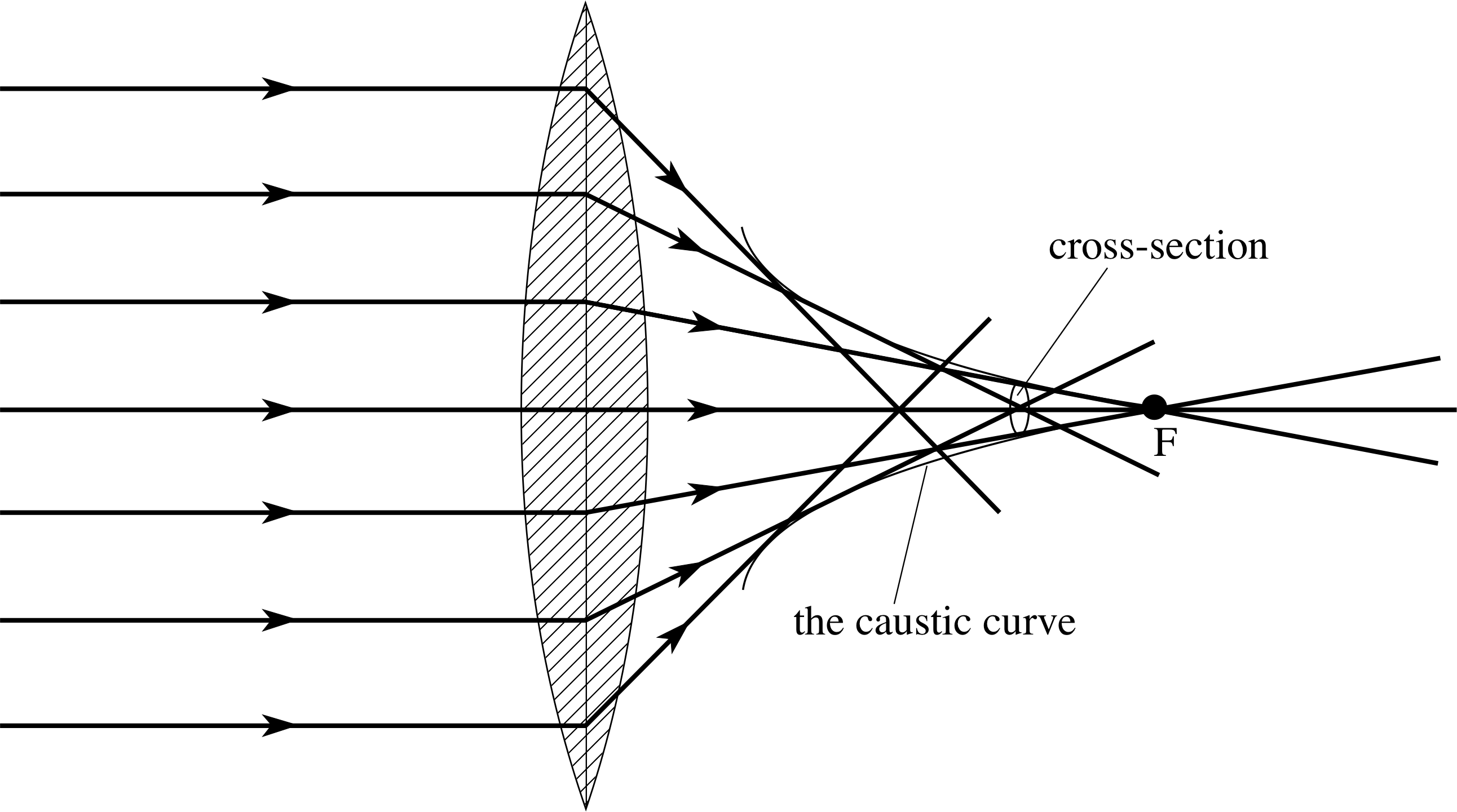
Figure 2 A lens displaying spherical aberration.

Figure 3a An idealized lens made up from a series of prisms

Figure 3b Section through a Fresnel lens.
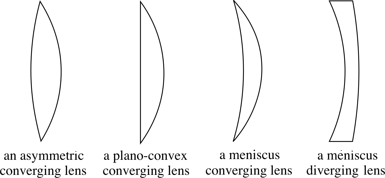
Figure 4 Varying the curvature of opposite faces of a lens.
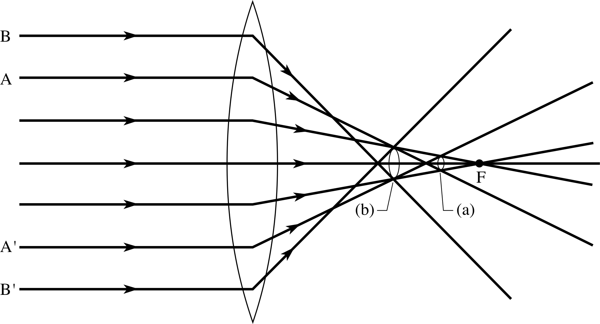
Figure 5 The effect of stopping down a lens to reduce spherical aberration. The circles of least confusion (a) from reduced aperture rays A and A′, (b) from almost full–aperture rays B and B′.
A conventional lens, with spherical surfaces, causes parallel rays which pass through the outer parts of the lens to cross the optical axis at points closer to the lens than rays through the central parts of the lens – the focal length of the lens increases smoothly as the rays get closer to the optical axis. This causes a point–like object to have an image that is not point–like – an effect known as spherical aberration. i
As Figure 2 indicates, parallel rays travelling close to the optical axis of a converging lens will come to a focus at a point F, but due to spherical aberration rays at greater distances from the axis will meet at points other than F, if they meet at all. In fact, after refraction, all such rays are tangential to a roughly conical surface, a longitudinal cross section of which is called a caustic curve. i A screen placed at right angles to the optical axis, at a point closer to the lens than the paraxial focus F, will show a disc of light, representing a transverse cross section of this conical focal region.
The diameter of the disc will depend on the precise location of the screen, but there will generally be some point at which the diameter of the disc is minimized. This minimum diameter image represents the least (spherically) aberrated image of a point object on the optical axis and is called the circle of least confusion. It is always found closer to the lens than the paraxial focus F.
Spherical aberration may be removed by grinding a lens so that it has aspheric surfaces (i.e. not spherical). Such aspheric lenses used to be both expensive and relatively difficult to make, but computer–controlled grinding and polishing machinery now makes this much easier.
Another approach is to assemble the lens from a set of prisms (Figure 3a), whose angles are chosen to give the correct deviation for any axial ray and so produce a common focus. This system is bulky and expensive.
A similar but simpler solution is to use large flat plastic lenses, called Fresnel lenses. i These have a series of stepped sections on their surface which act like a set of prisms, bending the light towards a common focal point. They are particularly useful where large apertures are required.
A frequently used method of reducing spherical aberration, using only spherical surfaces, is to divide the deviation of rays passing through the lens equally between the two faces of the lens. i This is achieved by giving the two faces different radii of curvature, so that the lens is asymmetric. This does not eliminate spherical aberration but lens shapes can be obtained which minimize spherical aberration (Figure 4). The curvatures required depend on the object distance for which they are to be used. The most generally effective lens shape is very nearly planoconvex. This same principle leads to spectacle lenses having a meniscus shape. Here, when the eyes are looking to one side, the angled pencil of rays which enter the eyes will still be nearly normal to the lens surfaces.
One simple way of reducing spherical aberration is to reduce the lens aperture, allowing only those rays which pass near the centre of the lens to contribute to the image (Figure 5). This will produce a less bright image and ultimately, if the aperture is made very small, diffraction effects (such as those discussed in the next subsection) may also become a problem. The process of reducing the size of an aperture is known as stopping down a lens.
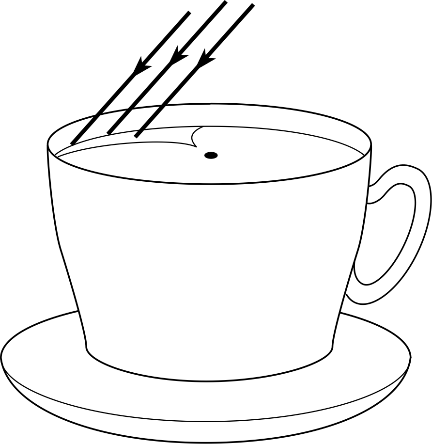
Figure 7 Spherical aberration producing a caustic curve by reflection from the inside of a cup of tea.
Spherical aberration also occurs in reflection from a spherical mirror, as is shown in Figure 6a.
You may have seen this effect produced by a cup of tea or coffee in bright sunlight. The parallel rays of sunlight are reflected across the surface of the drink (Figure 7), producing a ‘V’-shaped caustic curve, rather than a single focus. You may notice that the point of this ‘V’ is at the focal point for paraxial rays, half–way between the wall of the cup and the centre of curvature; rays which are further from the axis turn through smaller angles than do central rays.
If the reflecting surface is parabolical (i.e. of parabolic cross section, as in Figure 6b) there is no spherical aberration and all incoming parallel rays come to the same focal point. i
This constitutes a major advantage of paraboloidal reflectors and is used to good effect in reflecting telescopes and in satellite dishes.

Figure 6b Spherical aberration for a concave parabolic reflector. For a parabolic reflector, all the rays meet at the focus, just like a satellite dish.

Figure 6a Spherical aberration for a concave spherical mirror. For a concave spherical mirror the focal point for rays near the axis is half way between the centre of curvature and the mirror. Rays at the periphery are brought to a focus nearer the mirror.
Coma
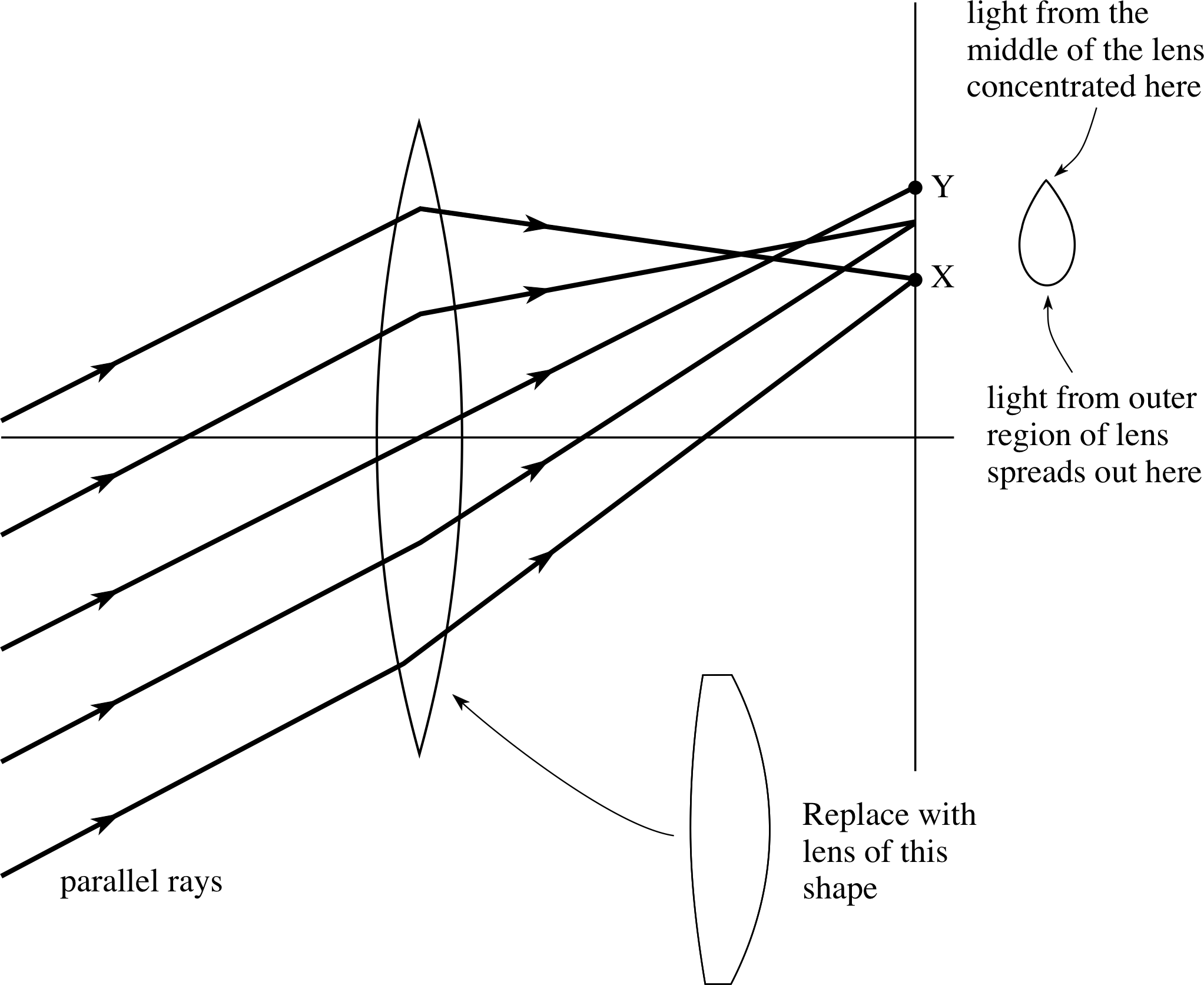
Figure 8 Diagram showing how coma is produced, and the lens shape to reduce it.

Figure 9a Chromatic aberration: dispersion by the lens results in different focal lengths for the different wavelengths present in white light, with the letters representing the colours of the rainbow (I stands for indigo)
A second source of aberration appears when the rays are non-axial. i This is due to an asymmetric deviation of non–axial rays by different parts of the lens, bringing them to a focus at different points, as shown in Figure 8. This aberration is called coma and its effect causes the straight edges of the image to be curved. If the object is bright, then little flares of light, looking like comet’s tails, may be seen pointing away from the axis. In Figure 8, only those rays passing through the central region of the lens reach Y to produce a concentrated spot of light. Light from the outer regions of the lens is spread out in the vicinity of X. In this way the light from a point object will give a small bright spot with a characteristic comet’s tail.
Coma can be reduced by changing the shape of the lens. Fortunately, the shape required to produce minimum spherical aberration is very nearly the same as that required for zero coma. It is therefore possible to produce individual lenses which display no coma and little spherical aberration – such lenses are very nearly planoconvex (see Figure 8).
Chromatic aberration
The third major source of aberration in lenses is caused by the refractive index of a material varying with wavelength (the process called dispersion). Both the refraction produced by a lens and its focal length will therefore depend on the wavelength and as light passes through the lens the various colours will be separated and imaged differently. This is called chromatic aberration, i and it produces coloured fringing around the image.
Question T2
On passing through a prism, violet light is refracted through a greater angle than red light. For which colour of light does the glass have the lowest refractive index? What does this tell you about the respective speeds of red and violet light in passing through glass?
Answer T2
The larger the refractive index of glass, the larger the angle through which light of a given wavelength is deviated or refracted when crossing an air–glass boundary (at non–normal incidence). As violet light is refracted through a larger angle than red light, the refractive index of the glass must be larger for the shorter wavelengths of violet light than for the longer wavelengths of red light. Since refractive index is the ratio of the speed of light in vacuo to the speed in the medium concerned, a large index means a low speed and therefore the violet light travels more slowly in the glass than the red light.
The lens maker’s equation (Cartesian version) for a lens made from glass of refractive index μ with surfaces of radii of curvature r1 and r2, gives the focal length f as:
Lens maker’s equation
$\dfrac1f = (\mu-1)\left(\dfrac{1}{r_1}-\dfrac{1}{r_2}\right)$(4) i

Figure 9b Chromatic aberration: separate images are formed for each wavelength.
Usually μ decreases with increasing wavelength and so a lens will have a shorter focal length for shorter wavelengths, with violet light being brought to a focus nearer the lens than red light, as shown in Figure 9a.
Figure 10 An achromatic doublet.
The different coloured images will thus have different sizes (Figure 9b) and when they overlap on a screen the result is an image with coloured fringes.
Chromatic aberration can be reduced by using a combination of lenses called an achromatic doublet (Figure 10). It consists of two lenses glued together with Canada balsam. i One lens is a converging lens made from crown glass, which has a lower refractive index and has less dispersion for a given focal length (i.e. lower dispersive power). The other lens is a weaker diverging lens made from flint glass, with a higher dispersive power. This combination is converging but the two component lenses can be chosen to have equal but opposite dispersions for two of the wavelengths present (e.g. red and blue) and dispersion which partially cancels at other wavelengths.
In summary, we see that if we want to produce optical instruments which are relatively free from chromatic aberration, spherical aberration and coma then the components should be achromatic doublets of roughly planoconvex shape. Since the process of dispersion requires refraction, we also note that mirrors are free from dispersion and hence from chromatic aberration.
Study comment In the remainder of this module we will assume that all lenses used have been designed to minimize these aberrations, but for simplicity we will refer to them simply as lenses.
2.3 Resolution and angular resolving power: the Rayleigh criterion
Another important limitation on the performance of lenses and mirrors arises from the wave nature of light. The passage of light is governed by the general principles of wave propagation and diffraction theory. Geometrical optics, using rays and straight line propagation, ignores these diffraction effects. When light passes through a lens or is reflected from a mirror, the boundary of the lens or the mirror restricts the wavefront and so acts as an aperture. Diffraction leads to divergence of light beams and to images which are not point images but rather extend over small regions. The smaller the aperture of any optical system then the more significant is the diffraction; it is particularly important where we are trying to distinguish fine detail of two images which are very close together, since each image has a minimum size which is set by diffraction. In particular, if two images are produced so close together that diffraction causes the two to overlap, then it may be impossible to distinguish that there are two separate images and we say that the system is unable to resolve the two images. This question of resolution has two aspects. First, there is a fundamental imaging resolution of the optical system, called its angular resolving power; this is due to diffraction and is determined by the aperture of the system. Secondly, the detection of the image (e.g. in the eye or on a film) is limited by the minimum area of the detector which will respond to light. We will consider detector resolution later, but first we discuss the angular resolving power of an imaging system.
When light from a point object passes through an optical system with a finite aperture the point image (or circle of least confusion), predicted by geometric optics, is replaced by a diffraction pattern of the aperture.

Figure 11a The Airy pattern formed by diffraction of a parallel beam of light falling on a small circular aperture of diameter d

Figure 11b The images of two point sources which are completely resolved
For a circular aperture this diffraction pattern, which is known as an Airy pattern, has circular symmetry and consists of a bright central region (the Airy disc), centred where the point image would be, and surrounded by bright rings which become fainter with increasing distance. Figure 11a shows the intensity across such a pattern.
Airy’s analysis showed that the first dark ring lay at an angle θ to the axis of the aperture, given by
Airy’s formula $\theta = \dfrac{1.22\lambda}{d}$ i
where d is the aperture diameter, λ is the wavelength of the light and θ is in radians. For a point object at infinity, a lens or mirror of focal length f produces an image at its focus, so the radius r of the first dark ring is
$r = \dfrac{1.22\lambda f}{d}$
The important fact to note about these equations for θ and r is that the larger the aperture of the objective or mirror, the smaller the spread of the Airy pattern and the more well–defined the image. This is as we anticipated, since diffraction increases with the reduction of the aperture.
If two closely adjacent images are produced by an optical instrument then each image will be an Airy pattern and the two images will be easily resolved if their Airy patterns are well separated (Figure 11b). i
If the images are sufficiently close that their Airy patterns overlap then the resultant intensity is normally the simple sum of the two intensity patterns. If the images are not too close the summation intensity will still show a central dip in intensity between the two central maxima and the two will be resolved. If the two are too close then there will be no such dip, but just a central maximum, and so they will appear as a single image.

Figure 11c The images of two point sources which are just resolved, according to the Rayleigh criterion.
Just what constitutes the resolution limit of two images is subjective, so Lord Rayleigh, i working in the last century, proposed an arbitrary but simple criterion for the resolution limit of the diffraction patterns of point sources of equal brightness, generated by circular apertures. He said that two such images – and therefore their sources – could be just resolved if the central maximum of one pattern coincided with the first minimum of the second (see Figure 11c). This critical condition for resolution is known as the Rayleigh criterion.
Since the central maximum and first minimum of the Airy pattern are separated by an angle θ, this angle is the smallest resolvable angle between two images and consequently it is also the smallest resolvable angle between two point objects. This angle is known as the angular limit of resolution, or sometimes as the angular resolving power of the optical system concerned.
The angular limit of resolution (or angular resolving power) θ for an optical system of entrance aperture diameter d, for light of wavelength λ is:
$\theta = \dfrac{1.22\lambda}{d}$(5)
where the angle θ is in radians provided λ and d are measured in the same units.
Notice that the angular resolving power of any optical instrument is a fundamental limitation of its aperture and is unaffected by any magnification produced. In any magnification the two overlapping Airy patterns will be equally magnified and the resolution unaffected – an indistinct image is equally indistinct, however much it is magnified!
These resolution limits of optical systems, using visible light, apply equally to systems using electromagnetic radiation of other wavelengths. i
Question T3
Compare the angular resolving power of the following imaging instruments (details of the italicized instruments are to be covered later). Take the wavelength of light as 5 × 10⁻⁷ m.
(a) the eye with an effective aperture of 0.5 c
(b) a pair of binoculars using a typical aperture of the front lenses
(c) the Yerkes Observatory optical telescope, with a diameter of roughly 1.0 m
(d) the Lovell Telescope, with a diameter of 76.2 m, using microwave radiation of wavelength 22 cm
Answer T3
(a) For the eye: θ = (1.22 × 5 × 10−7 m)/(5 × 10−3 m) = 1.22 × 10⁻⁴ rad
(b) For the binoculars (taking a typical front lens diameter of 5 cm):
θ = (1.22 × 5 × 10−7 m)/(5 × 10−2 m) = 1.22 × 10⁻⁵ rad
(c) For the optical telescope
θ = (1.22 × 5 × 10−7 m)/(1 m) = 6 × 10⁻⁷ rad
(d) For the radiotelescope
θ = (1.22 × 0.22 m)/(76.2 m) = 3.5 × 10⁻³ rad
For best results we want θ small.
Figure 6b Spherical aberration for a concave parabolic reflector. For a parabolic reflector, all the rays meet at the focus, just like a satellite dish.
Diffraction also plays a part in the performance of a parabolic reflector. The arguments concerning the diffraction pattern of a circular aperture are not restricted to incoming parallel radiation being brought to a focus; they apply equally to parallel radiation being produced from a point source, placed at the focus of a reflector. If we reverse the direction of light in Figure 6b we have the case of an ideal point source of radiation located at the focus of a parabolic reflector. Geometrical optics predicts that the reflected radiation will form a perfectly parallel beam (unlike the case of a spherical reflector). In practice, diffraction leads to the reflected radiation not being perfectly parallel, but spreading over a range of angles in accordance with the Airy pattern, with the angular direction of the first minimum with respect to the optical axis being given by Equation 5.
The difficulty of increasing the angular resolving power of radio telescopes has been solved in a number of ways. The most effective solution is to combine the signals from several radio telescopes separated by great distances. In this way it is possible to regard an array of radio telescopes as having an effective diameter of several kilometres. The extreme case is where telescopes in different continents are combined to give an effective diameter approaching that of the Earth.
Question T4
A satellite in an orbit at 25 000 km from the Earth transmits information by means of microwaves of 10 cm wavelength, generated at the focus of a parabolic dish of 3 m diameter. Find the angular spread of the central beam reflected from the dish and hence find the transverse dimension of the beam when it reaches the Earth.
Answer T4
The angle from the axis to the first minimum is given by Equation 5,
$\theta = \dfrac{1.22\lambda}{d}$(Eqn 5)
as
$\theta = \dfrac{1.22\lambda}{d} = \rm (1.22\times10\,cm/300\,cm)\,rad = 0.0407\,rad$
The angular spread of the central maximum is therefore twice this angle, i.e. 0.0814 rad.
The diameter of this central beam when it reaches the Earth will then be:
0.0814 × 25 000 km = 2035 km.
3 The eye
The eye is the most familiar optical instrument. It is remarkably sensitive and versatile but its limitations must be appreciated in order to understand the need for and the design of other optical instruments. We begin with the structure of the eye and then consider some of its common shortcomings.
3.1 The structure of the eye
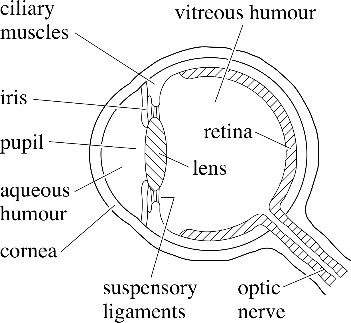
Figure 12 Section through the human eye.
Figure 12 shows a section through the eye. Light enters the eye through the transparent cornea, at which refraction first takes place. It then passes through the aqueous humour and, by way of the variable sized aperture or pupil in the iris (the coloured part of the eye) enters the lens (of the eye), which is held in place by suspensory ligaments. The focal length of the lens is altered by contraction or relaxation of the ring–shaped ciliary muscles which surround it, allowing the combination of cornea and lens to focus the light from an object on to the retina. In fact, the cornea produces a substantial part of the imaging power of the eye. Signals from the retina are relayed to the brain via the optic nerve. Much of the eye is filled with a clear jelly–like material – the vitreous humour.
Clear vision requires an optimum amount of light. The eye is dazzled by too much light. With too little light, the detail is lost, and so too eventually is the colour. The eye automatically controls the light intensity at the image by changing the size of the pupil. On a bright day the pupil is small, but in the dark it becomes large (dilated). i
The light–sensitive surface of the eye is the retina. This is a thin layer made up of about 125 million cells of two types, the rods and the cones_of_the_eyecones. The rods do not respond to the fine detail of the retinal image, but they are very sensitive and provide vision at low light intensities. The cones are found mainly in the central region of the retina, and consist of cells which are sensitive to either red, green or blue wavelengths but they are ineffective at low light levels.
To establish the performance of the eye try this test for yourself; if you normally wear glasses take them off before you begin.
Look out of the window. How far can you see clearly – for example, are the leaves on a distant tree sharply defined or indistinct? When looking at a distant object your eye should feel relaxed because the ciliary muscles are not tightened. When eyes are relaxed, the parallel light rays from a distant object can usually be brought to a focus on the retina. Is this true for your own eyes? The furthest point at which you can see clearly is described as your far point and for the normal eye this is at infinity.
In Subsection 2.1 you saw that the closest distance at which the unaided eye can focus is called the least distance of distinct vision D and that this position is called the near point. Both the near and far points can of course be changed using lenses, as in spectacles, but you may be more surprised to discover that they can also be changed by reducing the aperture of the eye. Try the following experiment.
Take a piece of card or paper and make a pinhole in it. i Close one eye and look through this pinhole with the other eye. Look first at a distant tree and examine the detail which is now visible. Try this now.
You will probably find that with the distant object much detail is lost – for example, if you could distinguish individual leaves on the tree beforehand, you probably can’t do so through the pinhole. As we saw in Subsection 2.3, the resolution of any optical system, that is its ability to distinguish two nearby objects, is limited by the aperture of the system. This pinhole experiment directly demonstrates the reduction in the resolution of the eye (or visual acuity), when its aperture is dramatically reduced. In the eye there are two principal contributions to this resolution limit. One of these is the angular resolving power of the eye lens itself, which is a diffraction limitation associated with any optical component of finite aperture. The other factor involved in this resolution limit is the detector resolution – in this case, the finite size of the individual retinal receptors. Once the image size becomes less than this receptor size, the eye can no longer distinguish any further reduction in size.
If the images of two nearby small objects are confined to the same retinal receptor then the two objects can no longer be distinguished. The resolution limit of the normal eye occurs when the two sources are separated by about 1′ of arc. i We are unable to see detail, or resolve two sources, with angular separations less than this. This angular limit corresponds to a distance of about 0.07 mm at the near point.
Question T5
Use the information given above to estimate, for the normal unaided eye: (a) the greatest distance at which the individual letters on a page can just be distinguished; (b) the size of the smallest object on the Earth which could just be seen from the Moon. (See Answer T1).
Answer T5
The resolution limit of the normal eye occurs when the two sources are separated by about 1′ of arc i.e. 0.07 mm at 25 cm.
(a) If we take the individual letters to be about 1 mm in size, separated by about 1 mm then, by proportion, the furthest distance of distinguishability is about 3.5 m.
(b) The Earth–Moon distance from Answer T1 is 3.5 × 10⁸ m and so the minimum distinguishable size is: 3.5 × 108 m × 0.07 mm/(0.25 m) = 98 km.
Now take the pinhole again and look at the effect on the near point by looking through the pinhole at the text on this page. How close to the text can your eye now come and still be able to focus the text? Try this now.
If you tried this you were probably amazed by the effect on the near point! Instead of being about 25 cm it may well have become about 2 cm – so close as to be almost at the surface of the eye. You were probably not expecting to find that a pinhole has a high magnifying power, but the text certainly looks much larger! According to our definition of magnifying power this is true, although the view is rather dim, since very little light is admitted.
The process by which we gauge the distance to an object involves a complex and subtle interpretative process in the brain. The size of the image on the retina is determined by the angle subtended by the object at the eye. This in turn depends not only on the distance to the object but also on its size. In depth or distance perception the brain interprets the information coming from both eyes, along with information coming from the muscular adjustments needed to point both eyes at the object. Our previous experience of the world is also involved in this interpretation.
Figure 3a An idealized lens made up from a series of prisms
Spherical aberration is minimized in the eye’s lens through an impressive piece of biological evolution. The refractive index of the lens material is not uniform but decreases away from the centre, so that the outer regions do not produce excessive refraction, such as would occur with a simple lens. Figure 3a may help you to understand this, if you consider the effect that progressively lower refractive indices for the prisms would have on the paths of rays passing through the system. It is interesting to note that this same technique, of grading the refractive index through a material, has recently been re–invented by scientists in fibre optics technology i – although for quite a different purpose!
3.2 Defects of vision: long sight and short sight
For some people the near point is much further away than 25 cm and only more distant objects can be focused on to the retina. This is called long sight or hypermetropia.
The extreme case of this is where the minimum focal length of the eye lens is longer than the eye cavity; it will then be impossible to focus any object, however distant. Long sight can be corrected using an auxiliary converging lens, as is shown in Figure 13. Light coming from an object placed at the normal near point, D, then appears to come from the eye’s own near point, NP, allowing a sharp image to be produced.
For some other people, the far point is much closer than infinity and only nearby objects can be focused on to the retina. This is called short sight, or myopia. Because the eye cannot relax sufficiently, the maximum focal length is shorter than the eye cavity and parallel rays cannot be focused at the retina. Short sight can be corrected using an auxiliary diverging lens as shown in Figure 14. Parallel rays coming from infinity then appear to come from the eye’s own far point FP, allowing a sharp image to be formed.
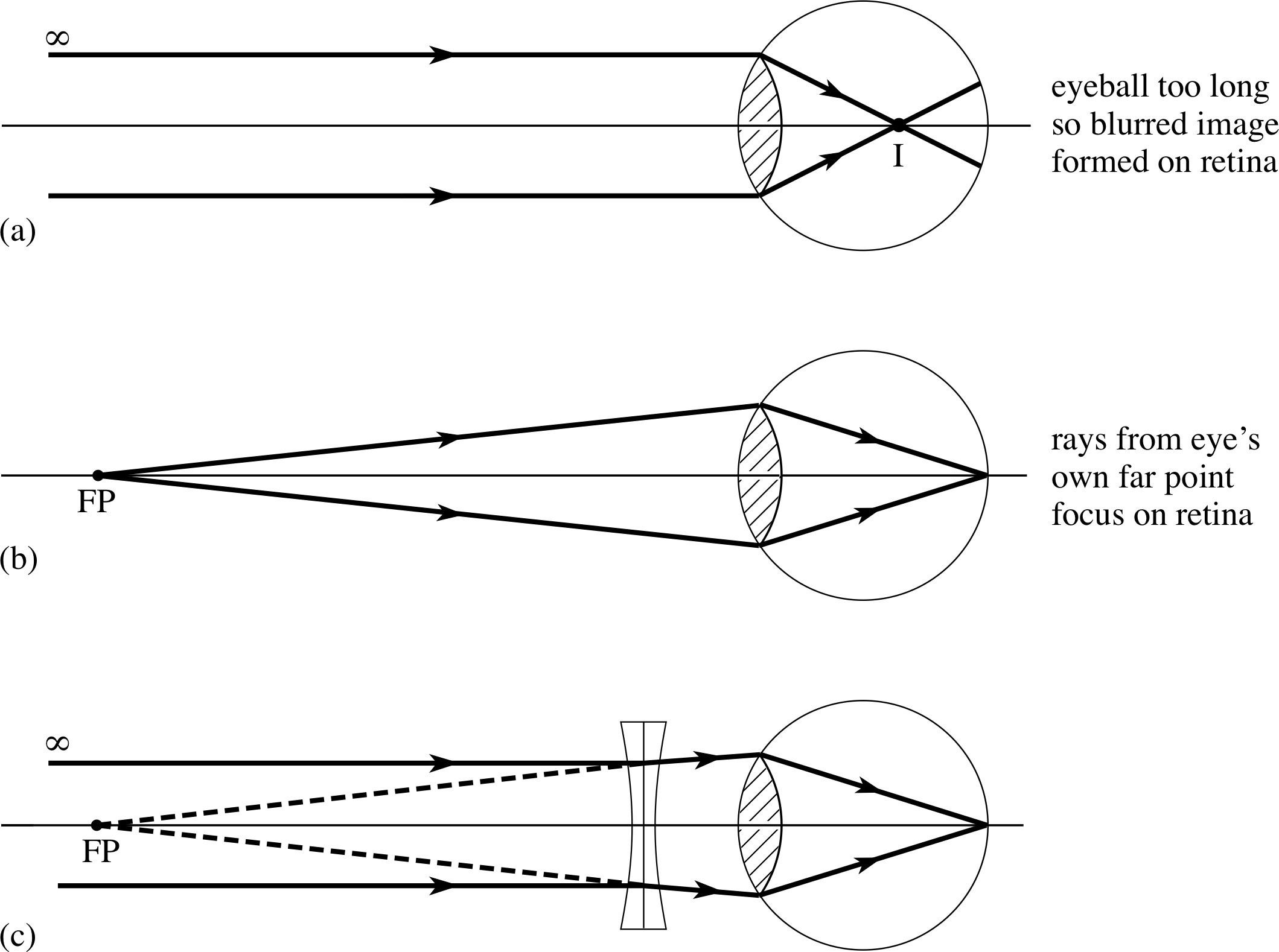
Figure 14 Short sight: (a) the image position in a myopic eye with an object at infinity; (b) rays from the eye’s far point FP (which is closer than infinity) focus on the retina; (c) a diverging lens makes incoming parallel rays appear to come from the eye’s far point and the short sight is corrected.
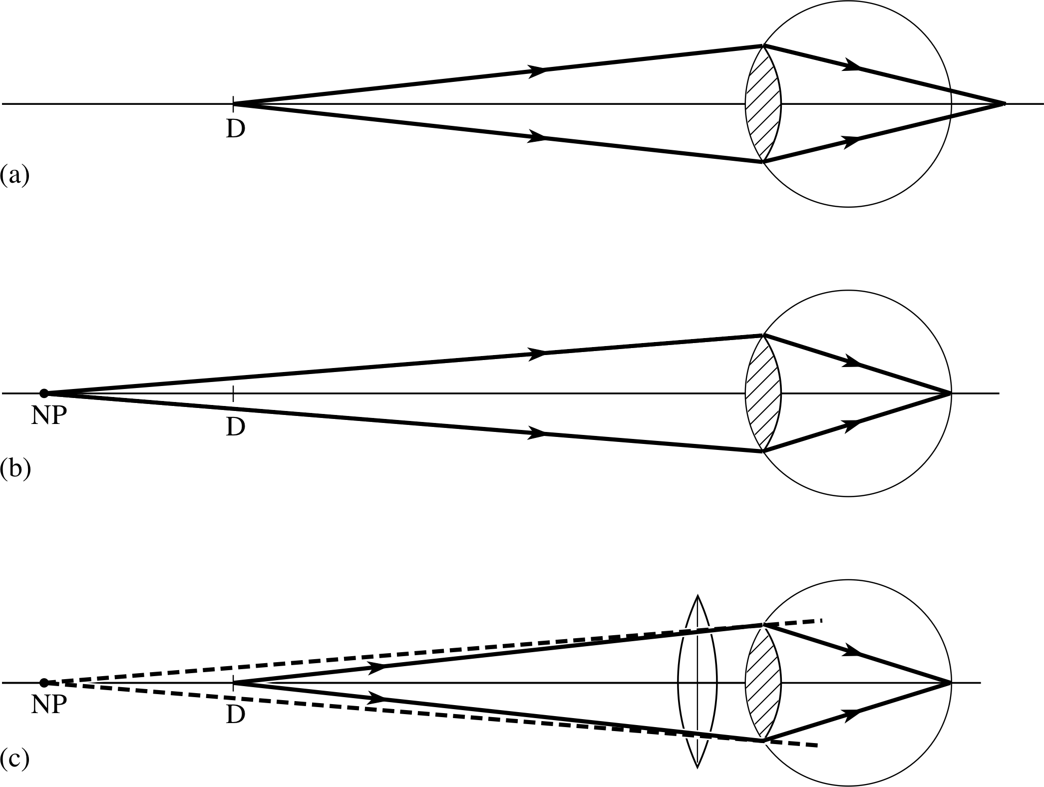
Figure 13 Long sight: (a) an object placed at the normal near point D produces a blurred image on the retina; (b) an object placed at the eye’s near point, NP, forms a sharp image on the retina; (c) the presence of a converging lens causes an object placed at D to appear to be at the eye’s near point.
4 Some simple optical instruments
In this section we describe some instruments which use only a single optical component. The simple pinhole could be taken to be the simplest such instrument, since its magnifying power (of around 10) stems from its ability to allow the eye to be brought much nearer to the object than normal. However, the loss of light and resolution mean that the pinhole has very limited usefulness and so we move on to consider the next simplest device.
4.1 The magnifying glass

Figure 15a Ray diagrams for a magnifying glass with: the object placed at the focal point and the image formed at infinity; It is assumed that the eye is placed very close to the lens so that D can be measured from the lens. (The symbol ∴ means ‘therefore’.)
Figure 1c Magnifying power is the ratio of the angles subtended (at the eye) by the image and the object when at the near point.
A simple magnifying glass consists of a single convex lens, with the object placed closer than the focal point, so that the image is virtual, enlarged and beyond the focal point. If we wish to observe the object with minimum eye strain we arrange that the eye is fully relaxed (unaccommodated), with the image formed at infinity, rather than consciously focused (accommodated). This requires the object to be placed at the first focal point F of the convex lens, as shown in Figure 15a.
We see that θI ≈ tan θI = h/f.
The magnifying power (given by Equation 3)
$M_{\rm power} = \dfrac{\theta_{\rm I}}{\theta_{\rm D}} \approx \dfrac{\tan\theta_{\rm I}}{\tan\theta_{\rm D}}$(Eqn 3)
is the ratio of this angle to the angle subtended by the object when placed at the near point, θD ≈ h/D, (Figure 1c) and so we have:
$M_{\rm power}= \dfrac{\theta_{\rm I}}{\theta_{\rm D}} = \left(\dfrac hf\right)\left(\dfrac Dh\right) = \dfrac Df$
The magnifying power is then simply given by the ratio of the distance to the near point (25 cm) divided by the focal length of the lens. A typical value of f for a simple magnifier is ~10 cm, giving a magnifying power of ~ 2.5. The magnifying power of a magnifying glass with the image at infinity is equal to the least distance of distinct vision divided by the focal length of the lens:
Mpower = D/f(6)

Figure 15b Ray diagrams for a magnifying glass with the object brought closer (i.e. between F and the lens) and the image formed at the near point. It is assumed that the eye is placed very close to the lens so that D can be measured from the lens.
If we allow the eye to be accommodated (not fully relaxed) then it is possible to obtain a larger magnifying power than D/f by bringing the magnifying glass closer to the object, so that the object distance is less than f. The largest sharply focused image will then be found when the image is at the near point, as is shown in Figure 15b. In this case h′/D ≈ θI and h/D ≈ θD hence:
$M_{\rm power}= \dfrac{\theta_{\rm I}}{\theta_{\rm D}} = \left(\dfrac{h'}{f}\right)\left(\dfrac Dh\right) = \dfrac{h'}{h}$
We see from Equation 1,
$M_{\rm tran} = \dfrac{h'}{h} = \dfrac{\upsilon}{u}$(Eqn 1)
that when the image is formed at the near point, the (maximum) magnifying power is the same as the transverse magnification. i
Question T6
A magnifying glass of 10 cm focal length produces a virtual image 30 cm from the lens. Find the position of the object and hence find the transverse magnification produced by the lens in this arrangement.
Figure 15b Ray diagrams for a magnifying glass with the object brought closer (i.e. between F and the lens) and the image formed at the near point. It is assumed that the eye is placed very close to the lens so that D can be measured from the lens.
Answer T6
The ray diagram of Figure 15b is similar to that for this system, except that the final image is formed just beyond the near point.
We substitute υ = −30 cm and f = +10 cm in the thin lens equation (1/υ) − (1/u) = 1/f and obtain:
1/u = − 1/(30 cm) − 1/(10 cm) = −4/(30 cm)
so thatu = −7.5 cm.
The transverse magnification is:
Mtran = h′/h = υ/u = −30 cm/(−7.5 cm) = 4
We can now find an alternative expression for the largest magnifying power of a magnifying glass from the thin lens equation (using the Cartesian sign convention): i
$\dfrac{1}{\upsilon} - \dfrac 1u = \dfrac 1f$(7)
Multiplying both sides of Equation 7 by υ and rearranging it gives us:
$\dfrac{\upsilon}{u} = 1 - \dfrac{\upsilon}{f}$
For maximum Mpower the final image has υ = −D, so we have:
Maximum magnifying power of a magnifying glass (when the image is at the near point):
$(M_{\rm power})_{\rm max} = \dfrac{h'}{h} = \dfrac{\upsilon}{u} = 1 + \dfrac Df$(8)
We see that the maximum magnifying power is obtained by adding one to the value of the magnifying power with the unaccommodated eye.
4.2 The pinhole camera
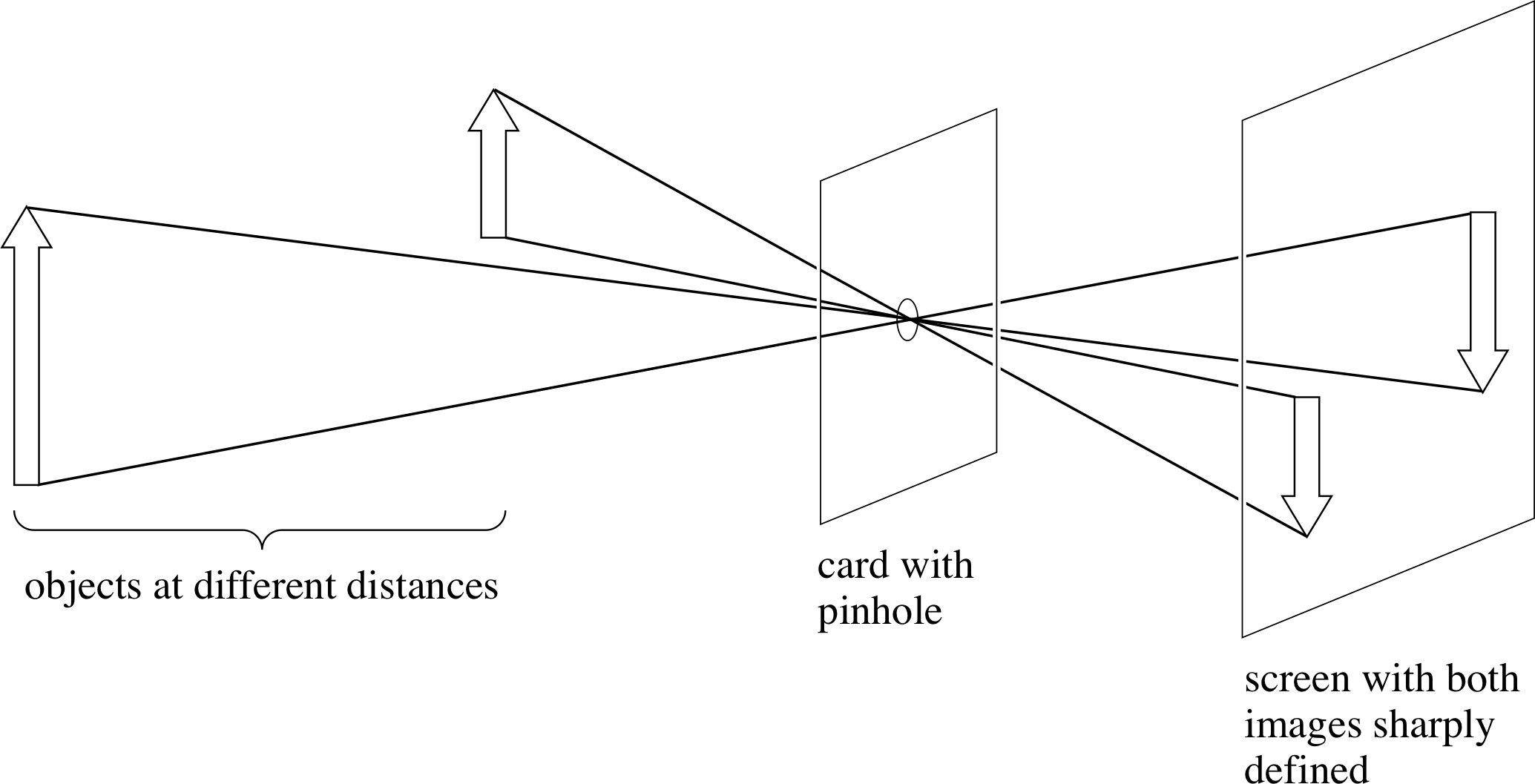
Figure 16 With a pinhole camera, everything is in focus.
The pinhole camera is the simplest camera and functions without the use of any lens, using the sharpness of image produced by a small hole as its basis. i A pinhole camera can be made, for example, by closing off a tube at one end with card, making a pinhole in the card and then forming a transparent screen at the other end with greaseproof paper. If the pinhole is pointed at a bright source, such as the filament of a clear electric light bulb, then a sharp image of the filament is produced on the paper and can be seen from the back. Figure 16 shows that the image is a projection of the object through the pinhole – each point on the object acts as the source of a single ray, which passes through the pinhole, taken as having negligible size, and arrives at a unique point on the image at the screen. The image size depends both on the angular size of the object and on the distance between the pinhole and the screen. The image is sharp for any object distance but the illumination is very low, since very little light is admitted.
✦ Suppose an attempt were made to admit more light by enlarging the pinhole substantially. Would this increase the illumination and would there be any other consequences?
✧ More light would be admitted and the image would be brighter. However, the image would no longer be as sharp since each point in the object could be a source of rays through different parts of the hole and these rays would each arrive at a slightly different part of the screen – hence an indistinct, blurred image would be produced.
To increase the illumination without blurring the image significantly requires the use of a lens, instead of the pinhole. The eye itself is one such example and the photographic camera is another.
5 Some more complex optical instruments
We now begin to consider real optical instruments, first the camera and then the microscope, the telescope, and the spectrometer. Most of these instruments use achromatic doublets, arranged to minimize aberrations, but in order to keep things simple our diagrams will show the combinations of lenses as if they were simple lenses.
5.1 The camera
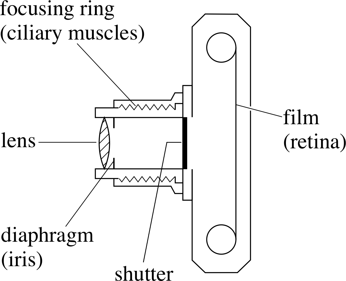
Figure 17 The components of a simple camera and their equivalents in the eye.
Figure 12 Section through the human eye.
The structures of the eye and the camera have much in common, as can be seen by comparing Figure 17 and Figure 12. Both need to perform the same three functions:
- focusing the image on to the photosensitive surface of a detector
- controlling the light intensity of the image
- detecting the light at the image
The camera lens, being made of glass, is not deformable in the same way as the eye lens and so its focal length is fixed. Focusing in the camera is achieved by changing the distance between the lens and the photographic film, which combines the roles of detector and recorder of the image. This film is coated with an emulsion containing silver compounds. When the emulsion of a black and white film is exposed to light and subsequently developed, small grains of silver are formed, making it darker and resulting in a negative image in which the light areas of the object appear as dark areas on the film and vice versa. Photographic films are made with different sensitivities to light, or with different speed_of_a_filmspeeds, with high speed film having the maximum sensitivity. i
The total amount of light energy falling on the film (i.e. the exposure) i is controlled in two ways. The shutter speed of the camera governs the time of illumination of the film (i.e. the exposure time) and this is the principal means used to control the amount of light reaching the film. A second control comes from the variable aperture or iris diaphragm, which is exactly analogous to the pupil in the iris of the eye. Both these means of controlling the exposure have secondary effects.
If the object moves during the exposure time then there will be a range of image positions produced on the film, leading to a blurred photograph. Fast shutter speeds are needed to photograph objects whose angular position is changing appreciably, such as occurs with rapidly moving objects or with nearby moving objects. The secondary effect associated with the iris diaphragm is on the range of object distances which can be simultaneously made sharp in the photograph. This point requires a little more explanation.
With the pinhole camera it was possible to produce an image which was simultaneously sharp for any object position. With a lens, this is no longer the case. A particular lens position, focused for a particular object distance, will produce an acceptably sharp image over only a limited range of object distances, called the depth of field of the lens at this focus position. Alternatively, an acceptably sharp image for a particular object distance, can be produced over a range of lens positions, called the depth of focus of the lens at this object position. i On the basis of the comparison with the pinhole camera, it is not surprising to find that both the depth of field and the depth of focus increase as the aperture of the lens is reduced. You should appreciate that this result has nothing to do with diffraction, but follows from geometrical optics. A given point on the object acts as a source of several rays, passing through different parts of the lens, with each ray arriving at a slightly different point on the image. As the aperture is reduced, the range of such rays passing through the system decreases and so the depth of field and the depth of focus both increase. Diffraction works in the opposite sense; the angular resolving power of a lens decreases as the aperture is reduced, so the visible detail and image sharpness is downgraded – but we need consider this only in the diffraction limit of the performance.
In this discussion of depth of field and depth of focus we have used the term ‘acceptably sharp’. This is necessary because the nature of the detector itself presents resolution limits. In the eye, for example, this is set by the size of the retinal receptors; in the film it is set by the size of the individual silver grains. If the detector resolution were to be increased, for example by using finer grains, then the depth of field and the depth of focus would change.
✦ If the detector resolution were to be increased, keeping other factors the same, would the depth of field increase or decrease?
✧ If the detector resolution were to be increased, then the ability of the detector to detect a lack of sharpness would also increase and so the range of distances giving an ‘acceptably’ sharp image (i.e. the depth of field) would decrease.
Figure 18 illustrates how the aperture of a lens controls the depth of field. The extreme rays through the aperture from a point object at A are brought to a focus on the detector at B. Due to detector resolution the detector sees this image as a small disc of light, rather than as a point. If the object is moved to A′ the image moves beyond the detector to B′ – the disc of light at the detector is now the unfocused image. Similarly, moving the object away to A′′ produces an image at B′′ and again there is a disc of light at the detector. If we choose the positions A′ and A′′ so that the discs of light are the same as the minimum detectable size, then the distance from A′ to A′′ is the depth of field. Examination of Figure 18 shows that if the lens aperture is reduced, the extreme rays make smaller angles to the optical axis and the depth of field will be increased: a full analysis shows that the depth of field is inversely proportional to the diameter of the lens aperture.
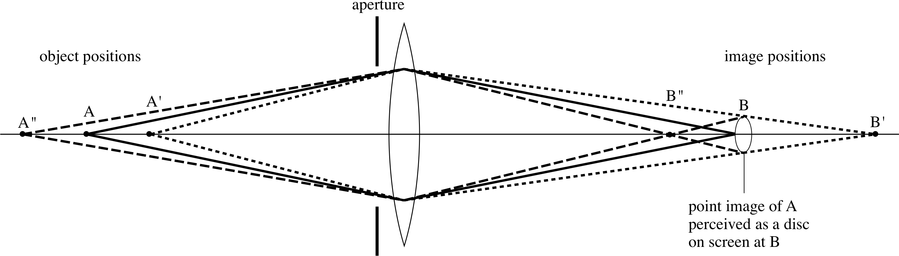
Figure 18 The depth of field over which there is no apparent change in image quality. i
One of the uses of the iris diaphragm of a camera is to change the depth of field deliberately. For example, in landscape photography a large depth of field is usually desirable so that both near and far objects are in focus, while in portraiture a small depth of field can be used to make the sharply focused sitter stand out from the blurred surroundings.
The effective aperture of a camera lens is usually specified by a quantity known as the f–number. This is obtained by dividing the focal length f of the lens by the diameter of the lens aperture d:
i.e.f-number = focal length/aperture diameter = f /d(9)
So for a lens with f = 56 mm and d = 20 mm, the f–number is 56 mm/20 mm = 2.8. This is often denoted by f/2.8. If a lens has an adjustable iris diaphragm then the lens has an adjustable f-number. Normally, lenses are classified according to their maximum f–number and so for example, we might say that a lens is an f/2.8 lens. If the aperture is very close to the lens then the amount of light passing through the lens is proportional to the area of the aperture in the diaphragm and therefore to the square of the aperture diameter d. From Equation 9 we see that for a given focal length, d is inversely proportional to the f-number, so the amount of light admitted is proportional to 1/(f-number)2.
As a consequence, the iris diaphragm of a camera usually has a number of predetermined aperture sizes or stops which successively halve the area of the aperture; if the aperture were changed by one stop to a higher f–number then, for the same exposure, twice the exposure time would be required. The usual f–numbers are 2.8, 4, 5.6, 8, 11, 16 and 22. The available exposure times (shutter speeds) therefore also change by factors of about two – typical values (in seconds) are 1, 1/2, 1/4, 1/8, 1/15, 1/30, 1/60, 1/125, 1/250, 1/500, and 1/1 000.
Question T7
The light conditions and the film in a camera are such that a good film exposure would be obtained with a shutter speed of (1/25) s at f/11. The photographer wishes to photograph a moving object and decides on a shutter speed of (1/1 000) s. What stop should be used? If the lens has a focal length of 50 mm, what is the diameter of the aperture at these two stop values?
Answer T7
In order to maintain the same exposure, when the shutter time is halved, the aperture must be doubled in area which is achieved by changing to the next smallest f-number. So, if f/11 is the proper stop for (1/125) s, then we require f/8 for (1/250) s, f/5.6 for (1/500) s and f/4 for (1/1000) s.
Since the f–number is the focal length f divided by the aperture diameter d, for f/11, d = 50 mm/11 = 4.55 mm; for f/4, d = 50 mm/4 = 12.5 mm.
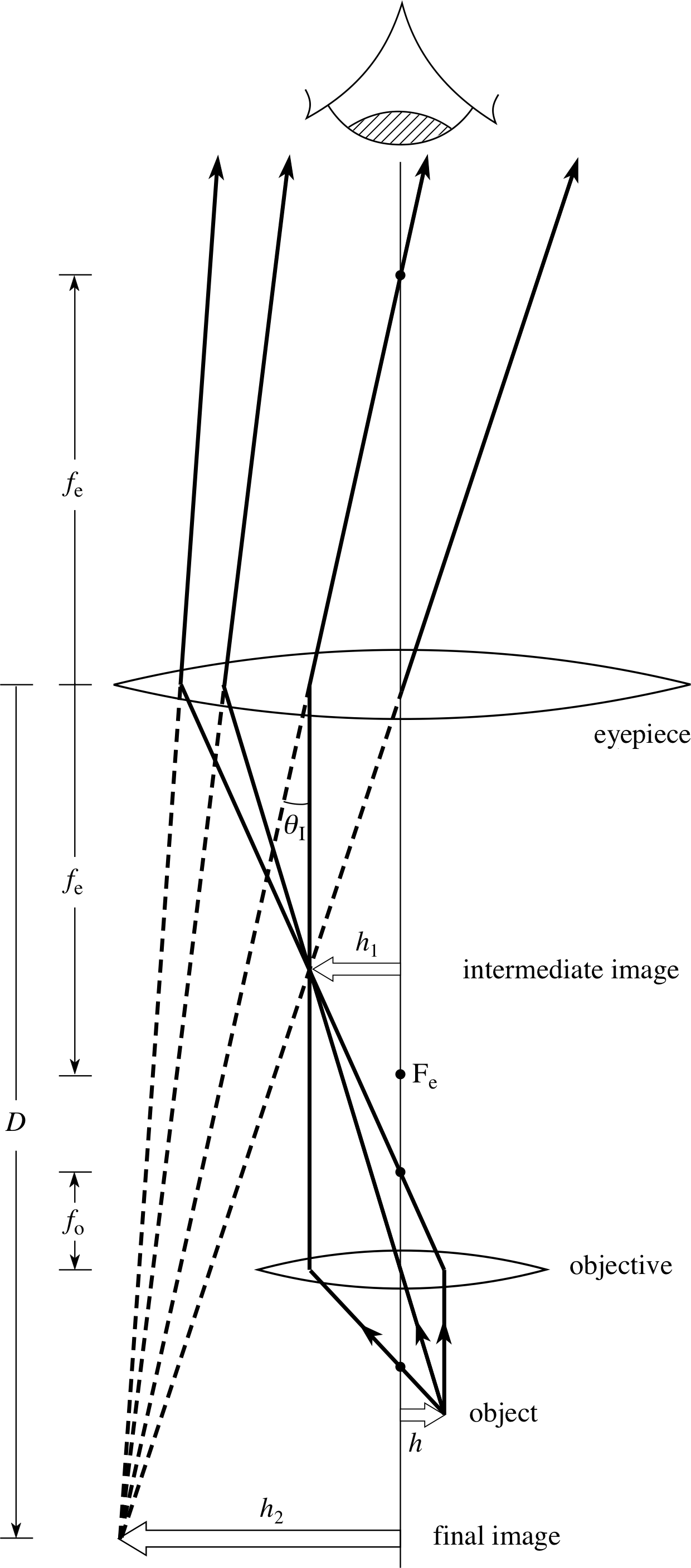
Figure 19 A compound microscope. The objective produces a real, inverted, intermediate image between Fe and the eyepiece. This acts as the object for the eyepiece which produces an enlarged, inverted virtual image. If this is at the near point of the eye, then maximum angular magnification is obtained. The eye has been shown at a large distance from the eyepiece, so that the construction rays may be included, but in reality the eye is placed at the eyepiece and the final image is at a distance D from the eyepiece.
5.2 The compound microscope
The lenses and ray diagram for the compound microscope are shown in Figure 19. The objective (lens) is the lens, or combination of lenses nearest to the object and the eyepiece (lens) is the one nearest to the eye. i
In microscopes (as well as in binoculars and refracting telescopes) it is the function of the objective to gather a large amount of light from the object and to create a real image. This image is then enlarged by the eyepiece (which may be used in the same way as a simple magnifying glass) to form a virtual image to be seen by the eye. The objective of a microscope is usually of very short focal length, with the focal length of the eyepiece much longer; both focal lengths are much shorter than the distance between the lenses.
To find the magnifying power of the microscope, we note that the angle subtended by the image is shown in the diagram as θI which, being a small angle, is equal to h2/D. This is assuming that this virtual image is being formed at the eye’s near point and that the eye is very close to the eyepiece.
To work out the angle subtended by the object with the unaided eye we simply have to imagine that the object is placed at the near point; consequently the small angle θ, which it subtends at the eye, will be given by h/D (from Figure 1c but not shown on Figure 19). We therefore have from Equation 3,
$M_{\rm power} = \dfrac{\theta_{\rm I}}{\theta_{\rm D}} \approx \dfrac{\tan\theta_{\rm I}}{\tan\theta_{\rm D}}$(Eqn 3)
that
$(M_{\rm power})_{\rm max} = \left.\dfrac{\theta_{\rm I}}{\theta_{\rm D}} = \left(\dfrac{h_2}{D}\right)\middle/\left(\dfrac hD\right)\right. = \dfrac{h_2}{h}$ i
The resulting fraction h2/h can also be written as (h2/h1)(h1/h), which shows that the transverse magnification of the compound microscope is equal to the transverse magnification of the eyepiece multiplied by the transverse magnification of the objective.
✦ A microscope is often used with the final image at infinity. Explain why this is desirable and say where the intermediate image should then be formed.
✧ An image viewed at infinity is viewed with the unaccommodated eye, that is an eye which is completely relaxed. This imposes less strain on the observer. For a final image to be formed at infinity, the intermediate image needs to be situated at the first focal point Fe of the eyepiece.
Question T8
A compound microscope has an objective and an eyepiece separated by a distance of 180 mm and having focal lengths of 2 mm and 25 mm respectively. Where must an object be placed so that the final image, as seen through the eyepiece, is formed at infinity?
Answer T8
For the final image to be formed at infinity, the intermediate image must be formed at the (first) focal point of the eyepiece, i.e. 25 mm from the eyepiece. This means that the intermediate image is (180 − 25) mm i.e. 155 mm from the objective. From the thin lens equation we have 1/u = 1/υ − 1/f, so that applying this to the objective and substituting f = 2 mm and v1=1155 mm gives:
1/u = 1/(155 mm) − 1/(2 mm) = (2 − 155)/(310 mm) = −153/(310 mm)
and sou = −2.03 mm
i.e. the object must be placed 2.03 mm in front of the objective.
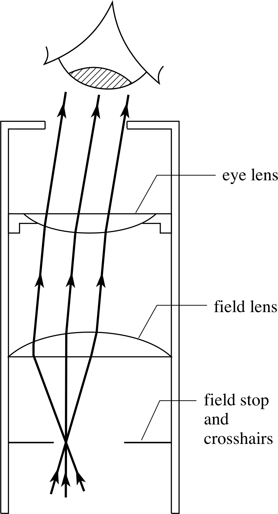
Figure 21 A Ramsden eyepiece showing the position of the field stop and crosshairs. In practice the eye lens would be an achromatic doublet.
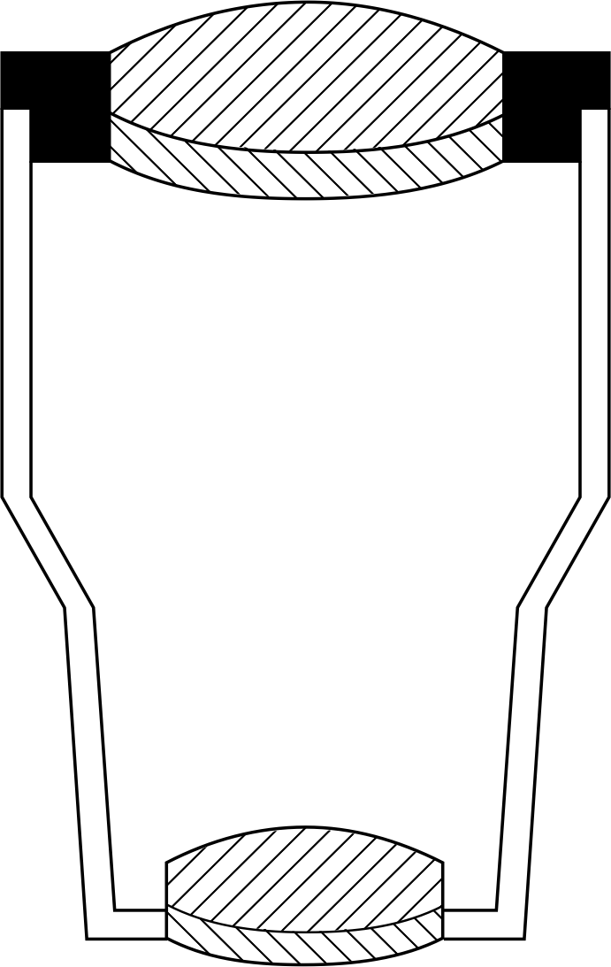
Figure 20 A low power objective.
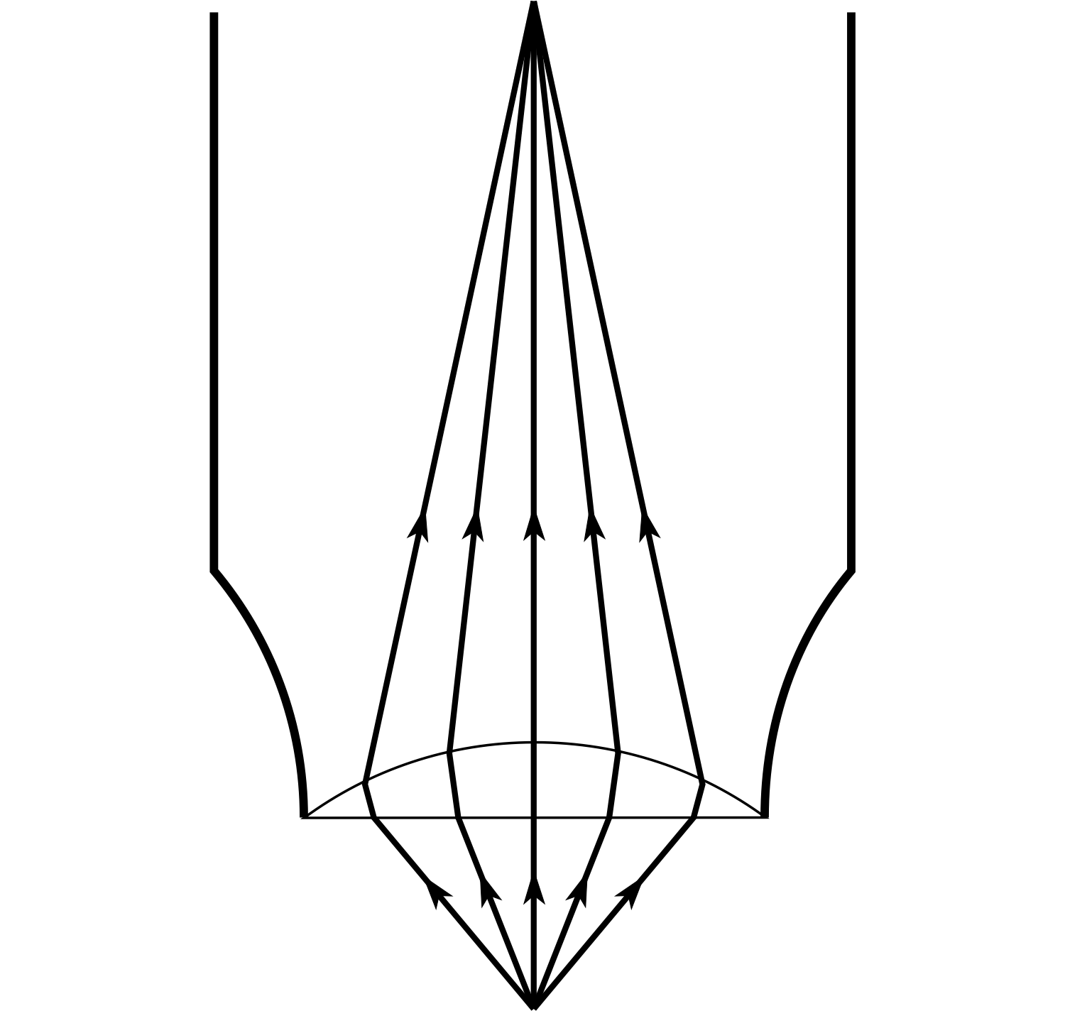
Figure 22 A planoconvex microscope objective. The paths of rays in the lens are almost parallel to the axis.
A typical low power objective (Figure 20) would have a focal length of about 1.5 cm, a magnifying power (magnification) of × 10, and would be made up from a pair of achromatic doublets, corrected for spherical aberration and coma.
There are many different designs for compound eyepieces. In instruments designed primarily for measurement (as opposed to simple viewing) it is an advantage to have crosshairs or a graticule incorporated into the optical system, and their image should be in focus at the same place as the image being viewed. The Ramsden eyepiece (see Figure 21) is such an example. It is made up from two lenses; the field lens and the eye lens.
The role of the field lens is to enable the eyepiece to accept rays over a wide range of angles whilst still remaining a relatively small sized component – to collect all this light, a single lens eyepiece would have to be large and heavy. An aperture which defines the maximum acceptance angle (and therefore the maximum field of view) is situated in front of the field lens and is called the field stop. The intermediate image is formed by the objective in the plane of the field stop, where the crosshairs are situated. The eyepiece lenses then make the rays from the intermediate image parallel before they enter the eye, so that both the final image and the crosshairs are seen in focus.
In microscopes, a large magnification is produced by placing the object very close to the objective lens and a large amount of light is collected from the object to make the image clearly visible. i These conditions would generate a lot of spherical aberration if a symmetrical objective were used. If you examine the external face of a microscope objective, it will probably appear flat. For short object distances, a planoconvex lens produces minimum spherical aberration because ray deviation is divided equally between the surfaces. i
By having the plane side facing the incident light (Figure 22) the curved surface will then receive rays which are more nearly parallel to the optical axis. The resultant image therefore displays less aberration than it would with a symmetrical objective, since rays distant from the axis will be brought to a focus nearer the focal point.
5.3 The refracting telescope
The simple refracting telescope, making use of two lenses, was one of the first optical instruments to be invented. The first systematic astronomical observations using such a device were made by Galileo Galilei (1564–1642). He heard that a telescope had appeared in Venice in the spring of 1609 and was able to construct his own, based on its description, although the previous year there had already been some debate between opticians in the Netherlands, including Hans Lippershey (1587–1619), as to who had been the first to develop an instrument for seeing at a distance. Almost anyone familiar with the magnifying properties of a single lens, and having access to two convex lenses for example, would instinctively examine the effect of putting them in succession and thereby ‘inventing’ a telescope (and/or microscope) of sorts. Telescope design consists of the selection of the lens types to be used.
The main impetus for developing such an instrument was two-fold; as an aid to navigation and trade, the terrestrial telescope was clearly of great value, whilst the greater sophistication it offered in making astronomical observations was of considerable importance at a time when debate was raging over new cosmologies. These two areas of application led to the development of two distinct types of telescope:
- The astronomical telescope, in which it is acceptable that the final image may be inverted.
- The terrestrial telescope, in which an upright final image is required.
Figure 23 A simple astronomical telescope. The objective has a long focal length whilst that of the eyepiece is much shorter.
Both cases view parallel light from a distant object and so the objective image is real, diminished and inverted, produced at its focal point FO. In the simplest form of astronomical telescope (Figure 23) this objective image is made to coincide with the focal point Fe of the eyepiece, which then produces an enlarged, virtual image at infinity, and this is viewed by an observer’s relaxed eye. The essential difference between such a telescope and a microscope is that in the telescope the intermediate image is produced at the objective’s focus, whereas in the microscope it is further away.
It follows that the transverse magnification of the objective is much less than 1 for the telescope and greater than 1 for the microscope.
Since the object being viewed by a telescope is at infinity, the angular magnification (see Subsection 2.1) is the most appropriate measure of the performance of the instrument.
From Equation 2,
$M_{\rm ang} = \dfrac{\theta_{\rm I}}{\theta_{\rm O}} \approx \dfrac{\tan\theta_{\rm I}}{\tan\theta_{\rm O}} = \dfrac{h'/z'}{h/z}$(Eqn 2)
and Figure 23, we can see that the angular magnification Mang is given by:
Mang = θI /θO
where θI = h/fe and θI = h/fO
i.e.angular magnification of a simple refracting telescope = fO /fe(10)
So, in order to make Mang as large as possible we need the focal length of the objective to be as long as possible and the focal length of the eyepiece to be as short as possible. If you have ever looked through a telescope at the night sky you will have noticed how small an area it covers. This is a direct consequence of the telescope having a large angular magnification, but it can be very frustrating when trying to find a particular star since it is hard to judge the relative position of one star to another without reference to the background stars. This is why some high power telescopes have a small low power sighting telescope attached to them, to help with initial alignment.
When trying to observe very distant or faint objects we need to collect as much light from them as possible. For this reason the objective lens of a telescope is made as large as possible. Unlike a camera, a telescope does not have an iris diaphragm to limit the size of the aperture and it is the objective lens itself which fulfils this role and therefore acts as the aperture stop.
In general, if we illuminate the aperture stop of an optical system, then its image, formed by any lenses which precede it, is called the entrance pupil. For a telescope, the objective is the aperture stop; there are no lenses preceding it and therefore the objective is also the entrance pupil. All rays entering an optical system have to pass through the entrance pupil, but the more extreme angled rays passing through the entrance pupil may be unable to travel all the way through the system.
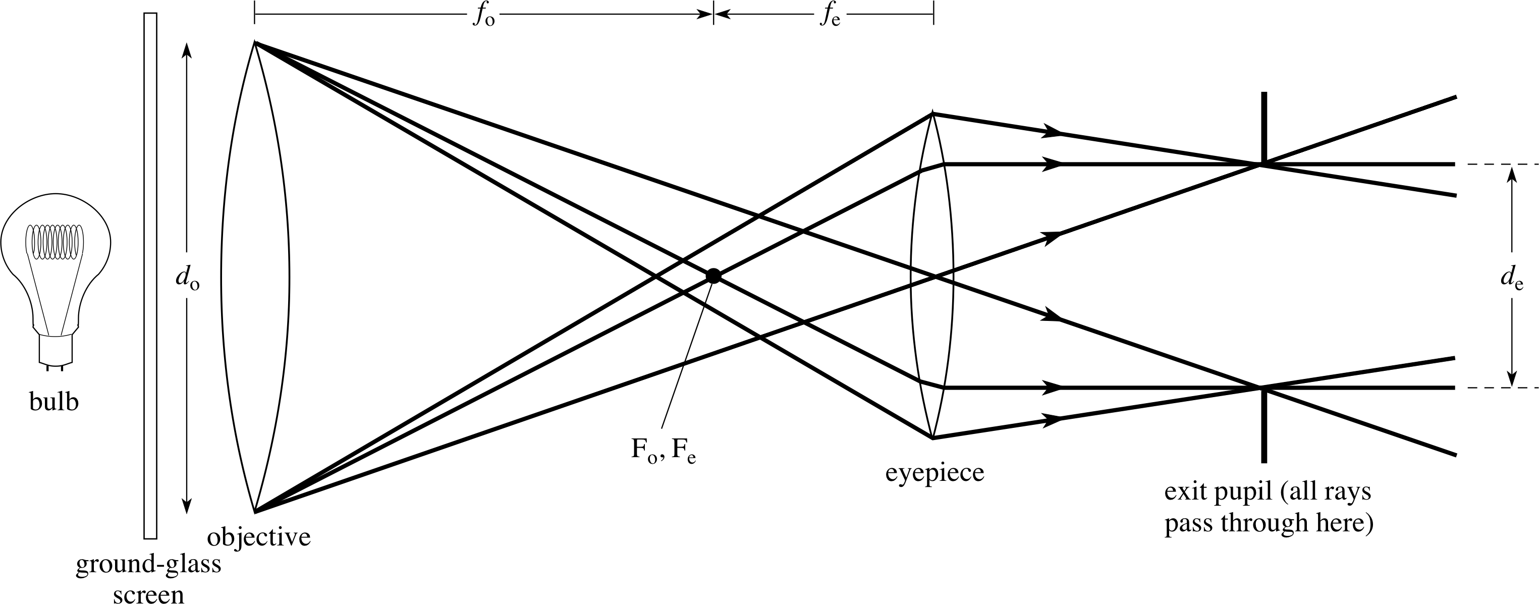
Figure 24 Diagram showing formation of the exit pupil in a simple astronomical telescope. The edge of the objective is being used to provide object points which are imaged by the eyepiece and the purpose of the ground–glass screen is to provide uniform illumination of the objective.
The exit pupil is similarly defined as the image of the aperture stop formed by all lenses which follow it. In a telescope the exit pupil is simply the image of the objective formed by the eyepiece, and a ray diagram showing this is given in Figure 24. It is clear from this figure, that of all possible rays entering the objective, those emerging from the telescope must be within the range of rays shown. Also the emerging light is most concentrated at the exit pupil and therefore this is where the eye should be placed so that the maximum amount of light – and therefore information – reaches it.
From similar triangles in Figure 24:
(dO/2)/fO = (de/2)/fe and therefore fO/fe = dO/de
but fO/fe = Mang so that Mang = dO/de
So the angular magnification of a simple telescope is given by:
Mang = objective diameter/exit pupil diameter.
This provides us with a practical method of measuring a telescope’s angular magnification. First we measure the diameter of the objective, then we illuminate the objective, either with a bulb and a ground glass screen or directly with a ‘pearl’ bulb, and measure the diameter of the objective’s image formed by the eyepiece on a screen. We then have the magnification from the ratio of these two diameters.
Question T9
An astronomical telescope has an angular magnification of 40 times. If the diameter of the objective is 12 cm and the length of the tube is 1 m calculate the focal length of the objective and the diameter of the exit pupil.
Answer T9
For a telescope, for which both the object and final image are effectively at infinity, the length of the tube is fO + fe = 100 cm. The angular magnification = fO/fe = 40, so fO = 40fe. Substituting for fO:
40fe + fe = 100 cm and fe = 100 cm/41 = 2.44 cm
HencefO = (100 − 2.44) cm = 97.56 cm.
To calculate the exit pupil size we know that the angular magnification is also given by dO/de = 40
so12 cm/de = 40 and de = 3 mm
A telescope with a wide aperture not only permits the collection of a large amount of light but also has the further advantage of a large angular resolving power, as described in Subsection 2.3, enabling the observer to distinguish between sources of light which are close together or see fine detail on the same object. In a telescope, the superimposed diffraction patterns of two close stars produced by the objective would be enlarged by the eyepiece. However, no amount of magnification can improve the resolution of the system. i
Perhaps you are now ready to invent a terrestrial telescope!
Question T10
Sketch a ray diagram showing how a third converging lens may be placed between the objective and eyepiece so as to produce an upright final image from a simple refracting telescope.
Answer T10
Looking at Figure 28 you will see how the introduction of a third converging lens between FO and Fe produces an erect image at infinity which makes the telescope suitable for terrestrial use.
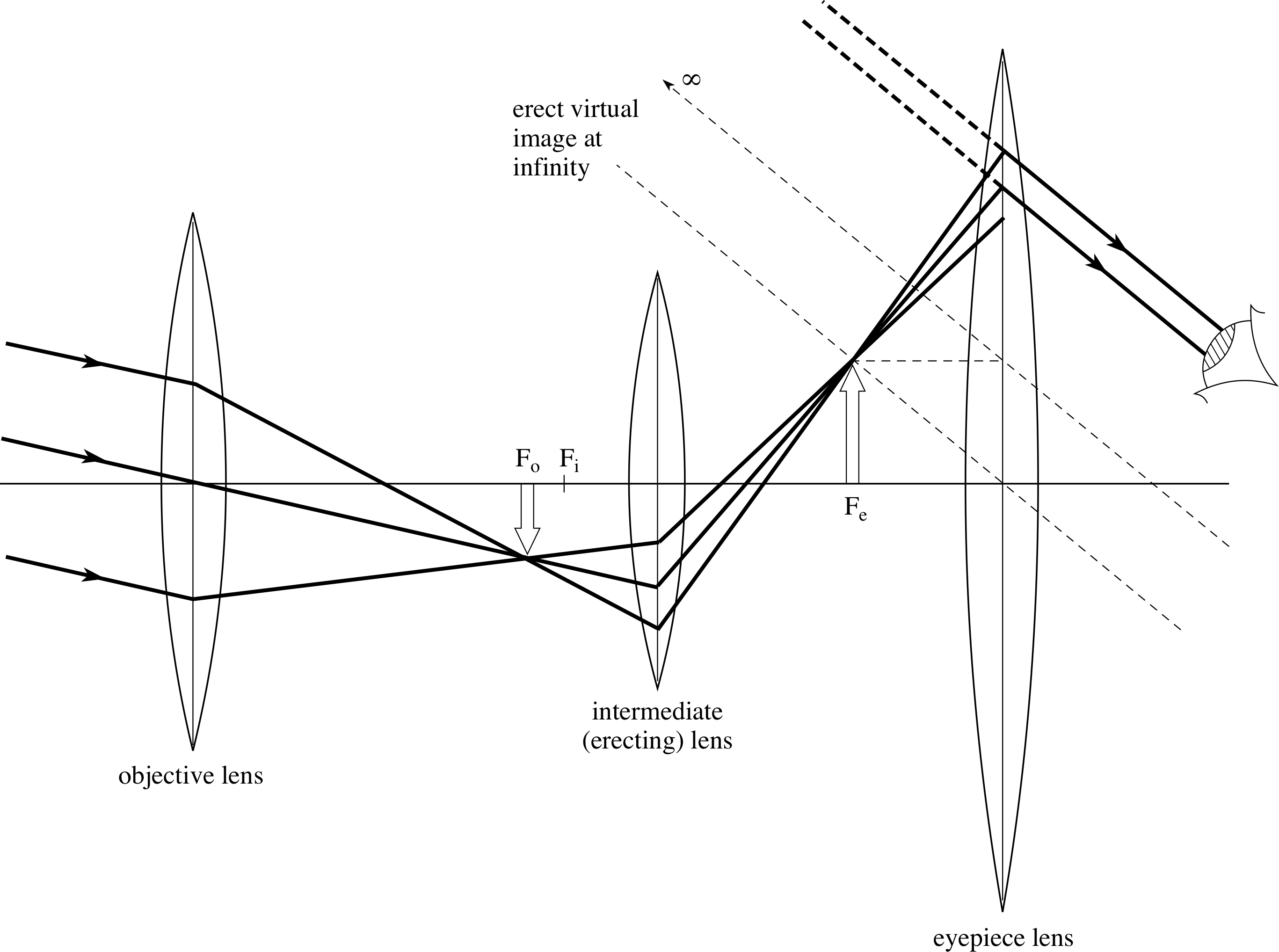
Figure 28 See Answer T10.
5.4 Binoculars
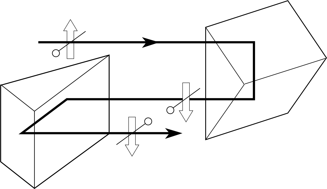
Figure 25 Image inversion by Porro prisms as used in some binoculars.
Binoculars consist of an identical pair of terrestrial telescopes, set side by side at a distance which can be adjusted to the user’s eye separation. Each telescope usually has a compound convex objective and eyepiece and the image inversion which this type of system usually produces, is removed by introducing erecting prisms between the lenses. The erecting system may consist of a pair of 45°–90°–45° prisms which, when used in the ‘total internal reflection’ mode, shown in Figure 25, are called Porro prisms. They are arranged at right angles to one another so that the first prism produces a vertical inversion and the second a horizontal inversion. The prisms have the additional advantage of reducing the overall length of the telescopes by ‘folding’ the optical path between the lenses.
The presence of the prisms means that the optical axis of an objective is displaced horizontally from that of the corresponding eyepiece. The prisms can therefore be oriented so that the distance between the objectives is greater than between the eyepieces and therefore further apart than the eyes, thus giving an enhanced stereoscopic vision. As with all terrestrial telescopes, the separation of objective and eyepiece is adjustable so that focusing over a range of object distances can be achieved.
5.5 The reflecting telescope

Figure 26a Off–axis reflector: the main reflector is turned so that the image is not on the optical axis.

Figure 26b Newtonian reflector: a plane mirror is placed at 45° to the optical axis, between the focus and the reflector. The image is formed at the focal point of the eyepiece so that, as before, a virtual image is formed at infinity to be viewed by the unaccommodated eye.

Figure 26c Cassegrain reflector: a convex reflector forms an image which coincides with the focal point of the eyepiece. A virtual image is formed at infinity, to be viewed by the unaccommodated eye.
The function of the objective of a refracting telescope is to gather as much as possible of the light emitted from the object and to focus it to form the intermediate image. The larger the diameter of the objective, the greater the amount of light it will collect. There are however disadvantages in using large lenses – these are (i) the difficulty and cost of producing them, (ii) their great weight, and (iii) the problems of minimizing their chromatic aberration.
Reflecting telescopes are designed as a relatively lightweight and accurate method of increasing the diameter of the entrance pupil in order that brighter and more distinct images can be seen. They also have the advantage of having no chromatic aberration (before the eyepiece), since the light does not have to pass through a dispersive medium. i As was discussed in Subsection 2.2, spherical aberration can also be avoided by using an aspheric surface.
The design problem of a reflecting telescope is that of observing the image which will be formed on the mirror’s optical axis if that axis points at the object. One solution is to turn the mirror so that the image falls outside the path of the incoming rays, as in Figure 26a, but this introduces aberrations. i
The solution devised by Sir Isaac Newton (1642–1727) had a small plane secondary mirror inside the tube which reflected the light rays through a right angle to an eyepiece positioned at the side of the telescope.
An alternative system, which maintains axial symmetry, is the Cassegrain reflector in which the light is reflected from a secondary curved mirror and brought to a focus through a small hole in the main reflector. i
5.6 The spectrometer
In the early days of astronomy one of the main tasks was to map the positions and relative brightnesses of the stars. However the light from stars gives us more information than simply position and brightness. By analysing the distribution of energy with respect to wavelength in the light from stars we can begin to find out much more about their relative motions, the elements contained within them and even their origins and ultimate destiny.
The one device which is central to unravelling the information contained within the light from stars is the spectrometer. As its name implies, its primary function is to disperse electromagnetic radiation and measure the intensities of the radiation in the spectra produced – its application to astronomy is just one of the many tasks for which it is employed.
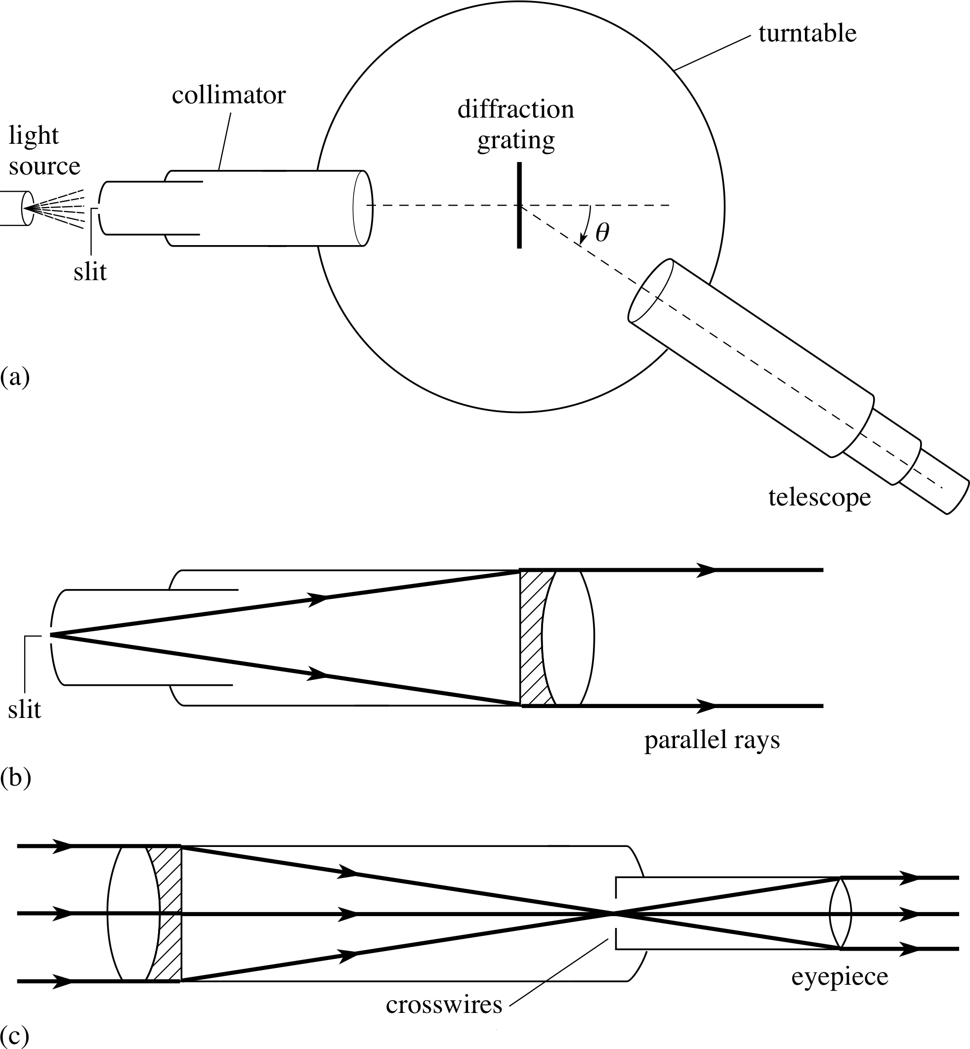
Figure 27 The spectrometer showing: (a) the arrangement of components as viewed from above; (b) the collimator and (c) the telescope.
An optical spectrometer (as shown in Figure 27) has three main parts:
- the collimator is a means of producing a parallel beam of light from a single slit, which is illuminated by the source of light under investigation. It is fixed to the base of the instrument.
- the turntable is a flat stage on which some dispersive element, such as a prism or diffraction grating is mounted. i The turntable can be rotated and the angle of rotation is measured from a scale.
- the telescope – this is able to rotate independently of the turntable and its relative position can be measured by means of a vernier against the turntable scale. The eyepiece of the telescope contains a cross wire with which the angular position of a particular wavelength of light can be found. If the spectrometer were to be used to measure intensities as well as positions then the telescope eyepiece would be replaced by an optical detector.
6 Closing items
6.1 Module summary
- 1
-
The magnification of an optical system may be described in one (or more) of three ways:
transverse magnification$M_{\rm tran} = \dfrac{h'}{h} = \dfrac{\upsilon}{u}$(Eqn 1)
angular magnification$M_{\rm ang} = \dfrac{\theta_{\rm I}}{\theta_{\rm O}} \approx \dfrac{\tan\theta_{\rm I}}{\tan\theta_{\rm O}} = \dfrac{h'/z'}{h/z}$(Eqn 2)
magnifying power$M_{\rm power} = \dfrac{\theta_{\rm I}}{\theta_{\rm D}} \approx \dfrac{\tan\theta_{\rm I}}{\tan\theta_{\rm D}}$(Eqn 3)
- 2
-
The spherical aberration of a lens is associated with the reduction in focal length of the outer parts of the lens compared with the central parts. Coma arises when oblique rays focus at different positions from axial rays. Chromatic aberration occurs because dispersion by the lens results in the focal length for violet light being shorter than the focal length for red light.
- 3
-
Spherical aberration and coma in convex lenses may be much reduced by ‘bending the lens’ to a near planoconvex shape. Chromatic aberration is minimized by cementing a high index convex lens to a low index concave lens to make a converging achromatic doublet in which the dispersions of the two glasses cancel one another.
- 4
-
The angular resolving power of any optical system is diffraction limited by its finite aperture. The image of a point source created by a system with a circular aperture shows this diffraction as a circular Airy pattern. The Rayleigh criterion for the resolution of two adjacent Airy patterns is that the maximum of one pattern falls on the first minimum of the other. The angular resolving power thus increases with the diameter of the aperture. The ultimate limit to resolution is set by the relationship between the size of the entrance aperture d and the wavelength λ of the radiation used:
angular resolving power$\theta = \dfrac{1.22\lambda}{d}$(Eqn 5)
- 5
-
The simple Subsection 3.2defects of vision, i.e. long and short sight, are attributed to the inability of the eye lens to focus images of near and far objects on the retina. Simple lenses enable these defects to be corrected.
- 6
-
The Subsection 4.1magnifying glass creates an enlarged, erect and virtual image of an object placed closer to the lens than the focal point.
- 7
-
The pinhole camera and its limitations may be used to provide insight into the construction and operation of the conventional Subsection 5.1camera. The f-number of the lens in such a camera specifies the aperture d of the lens in terms of the ratio f /d. This determines the depth of field, and exposure time for a given film and level of illumination.
- 8
-
The compound microscope is an instrument for looking at very small objects by using an objective to produce an enlarged real intermediate image which is then further enlarged by an eyepiece used as a magnifying glass. The performance of a microscope is given by its magnifying power. The Figure 21Ramsden eyepiece is an example of a compound eyepiece used in some microscopes and other optical instruments.
- 9
-
The telescope is an instrument for looking at distant objects. A large objective lens (in the refracting telescope) or concave mirror (in the reflecting telescope) collects light from the object to form a reduced real intermediate image at the focus. As in the microscope, this image is enlarged by an eyepiece acting as a magnifying glass. The magnification of a telescope is best described by its angular magnification.
- 10
-
The spectrometer is an example of an optical instrument which brings together many of the elements of other instruments. It is used to disperse and measure the wavelengths in a light beam.
6.2 Achievements
Having completed this module, you should be able to:
- A1
-
Define the terms that are emboldened and flagged in the margins of the module.
- A2
-
Apply the terms transverse magnification, angular magnification and magnifying power appropriately to optical instruments.
- A3
-
Describe the major lens defects of spherical aberration, coma and chromatic aberration and explain how they may be reduced.
- A4
-
Describe angular resolving power and the Rayleigh criterion. Calculate angular resolving power, given the aperture and wavelength.
- A5
-
Describe the main structural features of the eye.
- A6
-
Describe the main defects of vision and identify the means used to correct them.
- A7
-
Describe the behaviour of a magnifying glass using ray diagrams.
- A8
-
Describe the operation of the pinhole camera and the conventional lens camera. Interpret and use the terms: depth of field, depth of focus and f-number. Compare the behaviour of the eye and the camera.
- A9
-
Describe the arrangement of lenses used in a compound microscope and use this to construct ray diagrams showing its operation.
- A10
-
Describe the arrangement and operation of a Ramsden eyepiece.
- A11
-
Describe the arrangement of lenses used in astronomical and terrestrial refracting telescopes and draw ray diagrams showing their operation.
- A12
-
Describe the use of erecting prisms in binoculars.
- A13
-
Distinguish between the Newtonian and Cassegrain reflecting telescopes.
- A14
-
Describe the component parts and general operation of a spectrometer.
Study comment You may now wish to take the following Exit test for this module which tests these Achievements. If you prefer to study the module further before taking this test then return to the topModule contents to review some of the topics.
6.3 Exit test
Study comment Having completed this module, you should be able to answer the following questions each of which tests one or more of the Achievements.
| Function | Eye | Camera |
|---|---|---|
| light sensitive surface | photographic film | |
| ciliary muscles | distance setting ring | |
| corrects for spherical aberration | graded refractive index | |
| cone cells | fast film |
Question E1 (A5 and A8)
Complete Table 1 comparing the eye and the camera.
Answer E1
For the eye the light sensitive surface is the retina.
Focusing is achieved by control of the eye lens using the ciliary muscles. This ring of muscles contracts to shorten the focal length of the eye lens. With the camera, the image distance is changed by moving the lens backwards or forwards.
In a good quality camera, spherical aberration is corrected by using a converging meniscus lens. The cone cells and the film are the respective light detection systems.
(Reread Subsection 3.1 if you had difficulty with this question.)
Question E2 (A3 and A6)
Explain why a person with hypermetropia (long sight) needs to wear glasses which have converging lenses. Why are these lenses likely to be meniscus shaped? Sketch a diagram which shows how refraction of parallel rays takes place with a converging meniscus lens.
Answer E2

Figure 13c Long sight: the presence of a converging lens causes an object placed at D to appear to be at the eye’s near point.
With long sight the eye lens is only able to converge light to an image beyond the retina; additional convergence is required to cause rays from the near point to be brought to a focus at the retina. The additional converging lens is likely to have a meniscus shape (Figure 4), to reduce spherical aberration. The ray diagram is shown (for a biconvex lens) in Figure 13c.
(Reread Subsection 3.2 if you had difficulty with this question.)
Question E3 (A2 and A7)
A magnifying glass has a focal length of 10 cm. Compare its magnifying powers when used to view images formed at the far point (assumed to be at infinity) and at the near point (taken as 25 cm). Assume that the observer’s eye is placed very close to the lens.
Figure 1c Magnifying power is the ratio of the angles subtended (at the eye) by the image and the object when at the near point.
Figure 15a Ray diagrams for a magnifying glass with: the object placed at the focal point and the image formed at infinity; It is assumed that the eye is placed very close to the lens so that D can be measured from the lens. (The symbol ∴ means ‘therefore’.)
Answer E3
For an object at the near point distance D from the eye with no intervening lens, then, as shown in Figure 1c, the angle θD subtended by an object of height h is h/D.
The angle θ I subtended by the image formed at infinity by the lens, is seen from Figure 15a to be h/f, where f is the focal length of the lens. From Equation 3,
$M_{\rm power} = \dfrac{\theta_{\rm I}}{\theta_{\rm D}} \approx \dfrac{\tan\theta_{\rm I}}{\tan\theta_{\rm D}}$(Eqn 3)
and following the argument of Subsection 4.1, the magnifying power is
Mpower = θI/θD ≈ (h/f)(D/h) = D/f.
Substituting the values D = 25 cm and f = 10 cm gives
Mpower = 2.5
When the image is formed at the finite distance D from the lens and has a height h′, then θI = h′/D as shown in Figure 15b.
Again, θD = h/D so that
Mpower = (h′/D)/(h/D) = h′/h
This is shown in Subsection 4.1 to be 1 + (D/f), giving a magnifying power of 3.5.
(Reread Subsection 4.1 if you had difficulty with this question.)
Question E4 (A2 and A9)
Draw a ray diagram for a compound microscope to show how a virtual image may be formed at the eye’s near point. Using this diagram describe how the magnifying power is related to the linear magnification of each of the lenses.
Figure 19 A compound microscope. The objective produces a real, inverted, intermediate image between Fe and the eyepiece. This acts as the object for the eyepiece which produces an enlarged, inverted virtual image. If this is at the near point of the eye, then maximum angular magnification is obtained. The eye has been shown at a large distance from the eyepiece, so that the construction rays may be included, but in reality the eye is placed at the eyepiece and the final image is at a distance D from the eyepiece.
Answer E4
For the compound microscope see Figure 19. In drawing this it is best to start from the position of the final image (where D = 25 cm) and then trace the rays and construction lines back to the object.
From this it can be seen that the magnifying power is given by:
$\left(\large\substack{\rm transverse\\[4pt]\rm magnification\\[3pt]\rm of~objective}\right) \times \left(\large\substack{\rm transverse\\[4pt]\rm magnification\\[3pt]\rm of~eyepiece}\right)$
as shown in Subsection 5.2.
(Reread Subsection 5.2 if you had difficulty with this question.)
Question E5 (A2 and A11)
The focal lengths of the objective and eyepiece of an astronomical refracting telescope are 100 cm and 10 cm, respectively. Find (a) the angular magnification of the telescope, and (b) the angle subtended by the image, seen by an eye very close to the eyepiece, of a building which is 55 m high, situated at a distance of 5 km.
Answer E5
(a) The objective and eyepiece of a refracting telescope are normally separated by a distance equal to the sum of their focal lengths. For this arrangement the angular magnification is given by Equation 10 as fO/fe which is 100 cm/10 cm i.e. 10.
(b) The angle subtended by a 55 m high building at a distance of 5 km is 55 m/(5 × 103 m), i.e. 11 × 10−3 radians. The angle subtended by the image will be 10 times greater, i.e.
11 × 10−2 radians = (11 × 10−2 × 180/π)° = 6.3°
(Reread Subsection 5.3 if you had difficulty with this question.)
Question E6 (A4 and A13)
A Newtonian reflecting telescope has an aperture diameter of 25 cm. It is being used to observe two distant point sources which are close together. If the mean wavelength of light from these sources is 6 × 10⁻⁷ m calculate the minimum angular displacement they must have so that they may be clearly distinguished.
Answer E6
The angular resolving power is given by Equation 5,
$\theta = \dfrac{1.22\lambda}{d}$(Eqn 5)
In this case λ = 6 × 10⁻⁷ m and D = 0.25 m hence θ = 2.93 × 10⁻⁶ rad. This is, of course, the minimum angular
displacement by which two point sources can be resolved according to the Rayleigh criterion.
(Reread Subsection 2.3 if you had difficulty with this question.)
Question E7 (A14)
Describe the component parts and operation of an optical spectrometer.
Answer E7
Refer to Subsection 5.6.
Study comment This is the final Exit test question. When you have completed the Exit test go back and try the Subsection 1.2Fast track questions if you have not already done so.
If you have completed both the Fast track questions and the Exit test, then you have finished the module and may leave it here.
Study comment Having seen the Fast track questions you may feel that it would be wiser to follow the normal route through the module and to proceed directly to the following Ready to study? section.
Alternatively, you may still be sufficiently comfortable with the material covered by the module to proceed directly to the Section 6Closing items.