PHYS 7.3: Internal energy, heat and energy transfer |
PPLATO @ | |||||
PPLATO / FLAP (Flexible Learning Approach To Physics) |
||||||
|
1 Opening items
1.1 Module introduction
Consider the following observations which you might make if you went on a cycle tour starting at sea level and heading into the mountains.
- 1
-
At the start of your tour, after pumping up your bike tyres, you notice that the end of the pump has become quite warm.
- 2
-
You set off; as you cycle higher and higher, you observe that the air is getting cooler even though the Sun is still out.
- 3
-
The Sun goes behind a cloud and you immediately feel colder.
- 4
-
You put on a jacket and feel warmer.
All of these observations are commonplace and you would not be surprised by any of them but can you explain the physics of what is happening? By the end of this module you should be able to do so, but first you will need to spend some time learning about heat, work and internal energy.
The study of these concepts forms the basis of thermodynamics (from the Greek thermos: warm and dynamis: power). Although it is apparently concerned with simple ideas, thermodynamics is an area of physics which requires precise thinking. For this reason the terminology needs to be carefully defined. Some of the more important definitions are introduced in Section 2.
The relationship between heat, work and internal energy is expressed in the first law of thermodynamics which is described in Section 3. It is this law which can be used to explain observations (1) and (2) above. Section 4 deals with the transfer of heat by conduction, convection and radiation. An understanding of these processes helps to explain observations (3) and (4).
Study comment Having read the introduction you may feel that you are already familiar with the material covered by this module and that you do not need to study it. If so, try the following Fast track questions. If not, proceed directly to the Subsection 1.3Ready to study? Subsection.
1.2 Fast track questions
Study comment Can you answer the following Fast track questions? If you answer the questions successfully you need only glance through the module before looking at the Subsection 5.1Module summary and the Subsection 5.2Achievements. If you are sure that you can meet each of these achievements, try the Subsection 5.3Exit test. If you have difficulty with only one or two of the questions you should follow the guidance given in the answers and read the relevant parts of the module. However, if you have difficulty with more than two of the Exit questions you are strongly advised to study the whole module.
Question F1
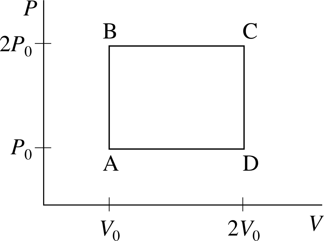
Figure 1 See Question F1.
The volume V and pressure P of n moles of an ideal gas of point particles (effectively a monatomic ideal gas) are gradually adjusted so that the gas goes through the cyclic process A–B–C–D shown in Figure 1. For each of the steps A–B, B–C, C–D, and D–A, calculate ∆T/T0, ∆U/nRT0, W/nRT0, and Q/nRT0, where R is the molar gas constant, T is the temperature of the gas, U its internal energy, W the work done by the gas, Q the heat supplied to the gas and T0 the temperature at A. Calculate the work done on the gas in one complete cycle. Show that the difference between the heat supplied to the gas, and the work done by the gas in one complete cycle is zero. Explain how you might arrive at this result without any calculation.
(You may assume that for an ideal monatomic gas, the internal energy is given by $U = \frac32nRT$.)
Answer F1
Applying the ideal gas equation to point A in the cycle gives P2V2 = nRT2. At point B: 2P2V2 = nRT2. Combining equations for points A and B gives us:
$T_1 = \dfrac{2P_0V_0}{nR} = 2T_0$
So∆T = T1 − T0 = 2T0 − T0 and $\dfrac{\Delta T}{T_0} = 1$
It follows that $\Delta U = \dfrac32 nR\Delta T = \dfrac32 nRT_0$
So$\dfrac{\Delta U}{nRT_0} = \dfrac32$
The work done by the gas in each part of the cycle is given by:
$\displaystyle W = \int_{V_{\rm initial}}^{V_{\rm final}}P\,dV$
During the step A–B there is no change of volume, so in that case W = 0.
From the first law of thermodynamics Q = ∆U + W = (3/2)nRT0.
So, in step A–B: $\dfrac{Q}{nRT_0} = \dfrac32$
| ∆T/T0 | ∆U/nRT0 | W/nRT0 | Q/nRT0 | |
|---|---|---|---|---|
| A−B | +1 | +3/2 | 0 | +3/2 |
| B−C | +2 | +3 | +2 | +5 |
| C−D | −2 | −3 | 0 | −3 |
| D−A | −1 | −3/2 | −1 | −5/2 |
| 1 cycle | 0 | 0 | +1 | +1 |
The other steps of the cycle can be treated in a similar fashion (though during the step B–C the pressure is constant, so in that case W = 2P0∆V) to obtain the results summarized in Table 2. The totals for a full cycle are also shown in the table and it can be seen that Q − W = 0. This might be deduced without calculation by considering the fact that the internal energy U is a function of state and will therefore always have the same value for a particular equilibrium state of the gas.
Thus the change in U for a complete cycle which arrives back at its starting point must be zero and hence, from the first law of thermodynamics Q − W must be zero. The fact that W and Q do not separately sum to zero over the cycle shows they are not functions of state.
Question F2
A wall, maintained at a constant temperature TW, is coated with a layer of insulating material of thickness x and of thermal conductivity κ. The outside of the insulation is in contact with the air at temperature TA. Heat is transferred by conduction through the insulation, and by natural convection through the air with convection coefficient h. Show that the rate of heat transfer per unit area is given by:
$\dfrac1A \dfrac{dQ}{dt} = -\dfrac{kh}{ (hx+k)}(T_{\rm W}-T_{\rm A})$
Answer F2
The heat flow through the insulation by conduction per unit area must be the same as the heat flow into the air by convection. If Ti is the temperature of the outer surface of the interface, then:
$\dfrac1A\dfrac{dQ}{dt} = \dfrac{-\kappa(T_{\rm W}-T_i)}{x} = -h(T_i-T_{\rm A})$
Rearranging gives us:
$T_{\rm W}-T_i = \dfrac{-x}{\kappa A}\dfrac{dQ}{dt}\quad\text{and}\quad T_i-T_{\rm A} = \dfrac{-1}{hA}\dfrac{dQ}{dt}$
Adding these two equations:
$T_{\rm W}-T_{\rm A} = \dfrac{-1}{A}\left(\dfrac x\kappa + \dfrac1h\right)\dfrac{dQ}{dt} = \dfrac{-1}{A}\left(\dfrac {hx+\kappa}{\kappa h}\right)\dfrac{dQ}{dt}$
So$\dfrac1A\dfrac{dQ}{dt} = \dfrac{-\kappa h}{hx+\kappa}T_{\rm W}-T_{\rm A}$
Question F3
The tungsten filament of an electric lamp has a length 0.5 m and a diameter 6.0 × 10⁻⁵ m. The power rating of the lamp is 60 W. Assuming the radiation from the filament is equivalent to 80% that of a perfect black body radiator at the same temperature, estimate the steady temperature of the filament. (Stefan’s constant is σ = 5.7 × 10⁻⁸ W m−2 K−4 and you may assume that the emissivity of the environment is 1).
Answer F3
For an object of area A at a temperature T surrounded by an environment of temperature T0 the net power emitted is
P = 0.8 × 1 × A σ (T4 − T04)
from which $T^4 = \dfrac{P}{0.8A\sigma} + T_0^4$
Although we aren’t told the value of T0, we can reasonably assume it is around room temperature, in which case it will have a negligible effect on the calculation at the required accuracy. This is easily seen by assuming a value of T0 = 300 K and using the other given data:
$T^4 = \dfrac{60}{0.8\times2\pi\times3.0\times10^{-5}\times0.5\times5.7\times10^{-8}} + 300^4$
where T4 is measured in K4.
HenceT4 = (14.0 × 10¹² + 0.0081 × 10¹²) K4 = 14.0 × 10¹² K4 (to 2 significant figures)
SoT = 1900 K (to 2 significant figures).
1.3 Ready to study?
Study comment To begin the study of this module you will need to understand the following terms: acceleration, conservation of energy, density, force, ideal gas, kinetic energy, mass, mole, momentum, potential energy, power, pressure, relative molecular mass, temperature (including the concept of absolute temperature), volume and work (in the mechanical sense, as the product of force and displacement in the direction of the force).
If you are uncertain about any of these definitions then you can review them now by reference to the Glossary, which will also indicate which FLAP modules to go to for further explanation. You should also be familiar with the equation_of_state_of_an_ideal_gasequation of state for an ideal gas PV = nRT, and be able to carry out simple calculations based on this equation, though it will be introduced at the appropriate point in the text. The mathematics used in this module requires you to be able to manipulate simple algebraic equations and to use the notation (though not the techniques) of differentiation. The concept of a definite integral is also introduced, though you will not be required to perform any integrations and do not need to be familiar with the techniques of integration in order to study this module. The following questions will let you see whether you need to review some of these topics before embarking on this module.
Question R1
A 1500 kg car accelerates uniformly from rest to a speed of 10 m s−1 in 3 seconds. Find (a) the work done on the car in this time, (b) the average power delivered by the engine in the first 3 seconds.
Answer R1
(a) After 3 seconds the kinetic energy is:
$E_{\rm kin} = \frac12m\upsilon^2 = \rm \frac12\times1500\times10^2\,J = 75\times10^3\,J$
However the kinetic energy must have come from the work done on the car by the engine, so the work done on the car is also 75 × 102 J.
(b) The average power during this period is the energy supplied per second. This is 75 × 102 J/3 s = 25 kW.
Question R2
Calculate the number of moles of oxygen molecules in a 2.00 kg sample of oxygen at atmospheric pressure and room temperature. (Take the relative molecular mass of oxygen to be 32).
Answer R2
The molar mass Mm (i.e. the mass per mole) of a substance in grams per mole is numerically equal to the relative molecular mass μ of that substance, i.e. Mm/(g mol−1) = μ. So, for oxygen Mm = 32 g mol−1 = 0.032 kg mol−1, and therefore the number of moles in a 2.00 kg sample of oxygen is:
$\rm \dfrac{2.0\,kg}{62.5\,mol} = 0.032\,kg\,mol^{-1}$
(The reason for stating that the gas is at atmospheric pressure and room temperature is that under these conditions you can be confident that gas is mainly composed of O2 molecules rather than separate atoms.)
Question R3
Explain what is meant by absolute temperature.
Answer R3
Absolute temperature is temperature measured on the scale where absolute zero (loosely, the temperature at which molecular motion is minimized) has the value zero and the triple point of water (close to the freezing temperature under atmospheric pressure) has the value 273.16 K. The units are kelvin (K).
Question R4
Working to the nearest whole number, what is the equivalent absolute temperature to 27 °C?
Answer R4
T/K = T/°C + 273.15, so a temperature of 27 °C is roughly equivalent to 300 K.
Comment If you had difficulty with any of these Ready to study questions, consult the Glossary.
2 Some basic ideas of thermodynamics
2.1 Systems, states and equilibrium
Thermodynamics is the branch of science that deals with the macroscopic (i.e. large scale) aspects of temperature, energy and the transfer of energy. It is not concerned with microscopic (atomic scale) behaviour, and the whole subject can be developed logically without mentioning atoms or molecules, though we shall not adopt any such puritanical stance in this module.
The subject of any particular thermodynamic investigation is generally referred to as the system. The rest of the universe is then referred to as its environment. A system may be almost anything, a car engine, the air in a bicycle pump, the Earth’s atmosphere or a human being. The environment sounds rather grand, but in practice we usually need only take account of that portion of the universe which has a significant effect on the system, particularly with regard to energy transfer. In the case of a car engine, this ‘effective’ environment might be the petrol tank, the drive shaft and the surrounding air; in the case of the air in a bicycle pump it might be the pump itself and the air in the tyre to which the pump is attached.
The systems that are studied in thermodynamics are generally ones that can exist in several different states, each of which is specified by the values of various macroscopic properties of the system. For example, a fixed quantity of air trapped in a bicycle pump might be at a high temperature or a low one, its volume might be relatively large or relatively small, and its pressure might be quite high or quite low. By quoting values for these macroscopic properties (temperature, volume and pressure), or at least for as many of them as are independent, we can specify uniquely the state of the air in the pump and thereby enable any other investigator to reproduce the conditions we are describing. Macroscopic properties that can play this role have to be carefully chosen, and are sometimes referred to as thermodynamic coordinates.
In this module we will be concerned mainly with systems in, or close to, thermodynamic equilibrium. When a system is in thermodynamic equilibrium neither its macroscopic properties, nor the state they define, change with time; any such unchanging state is called an equilibrium state. By saying that a system is ‘close’ to equilibrium we imply that its bulk properties (and hence its state) may change with time, but only so slowly that the instantaneous state of the system can be approximated by an equilibrium state. A process in which the state of a system changes but is always very close to an equilibrium state is said to be a quasistatic process. Clearly, not all processes are quasistatic but a surprisingly large number are, and we can learn a lot about the real world even if we restrict our considerations to equilibrium states and quasistatic processes.

Figure 2a A system consisting of a fixed quantity (i.e. a fixed number of moles n) of ideal gas at pressure P and temperature T contained in a cylinder of variable volume V.

Figure 2b The (truncated) equilibrium surface of the system, representing its possible equilibrium states. The lines drawn on the surface correspond to constant values of P, V or T.
2.2 The ideal gas – an illustrative example
Thermodynamics is a powerful discipline, based on laws and concepts of wide applicability. However, when meeting thermodynamic concepts for the first time it is usually a good idea to keep a particular example in mind; otherwise the generality of the concepts can make them seem abstract and remote. The simple system traditionally used to introduce thermodynamic ideas is one consisting of a fixed quantity of ideal gas, at pressure P and temperature T, enclosed in a cylinder of variable volume V (see Figure 2a). If the cylinder contains n moles of gas, then, provided the system is in equilibrium, the pressure, volume and temperature of the gas will be related by the equation of state of an ideal gas:
PV = nRT(1)
where R = 8.314 J K−1 mol−1 is the molar gas constant. Note that the temperature in Equation 1 must be expressed in kelvin (K) for the equation to be valid. The behaviour of many real gases can be investigated, at least approximately, by treating them as ideal gases.
The relationship between P, V and T given by Equation 1 can be shown graphically by using a three–dimensional graph of the sort shown in Figure 2b. For a given value of n (i.e. for a fixed quantity of gas) each set of values for P, V and T that satisfies Equation 1 specifies a single point on the graph and corresponds to a unique equilibrium state of the system. The set of all such points (i.e. the set of all equilibrium states of the fixed quantity of gas) constitutes a continuous two–dimensional surface in the three–dimensional PVT space of the graph. Such a surface is called the PVT surface or equilibrium surface of the gas. The surface shown in Figure 2b has been truncated for ease of display, but ignoring that, every possible equilibrium state of the system is represented by a point on the equilibrium surface and, conversely, any point not on the equilibrium surface does not represent a possible equilibrium state of the system.
✦ Suppose that the fixed quantity of ideal gas whose equilibrium surface is shown in Figure 2b undergoes a particular quasistatic process that takes it from some initial equilibrium state to some other equilibrium state. In general terms, how could you indicate that process on the PVT graph? What property of the graphical representation would show that the process was quasistatic?
✧ The process could be shown as a continuous pathway on the graph, starting at the initial equilibrium state and ending at the final equilibrium state. The fact that the process is quasistatic means that at every stage the state of the gas is very nearly in an equilibrium state; that’s why the pathway representing the quasistatic process would have to be confined to the equilibrium surface.
Looking at Figure 2b, or at the equation of state it represents, it is easy to see that for a given value of n (i.e. for a given equilibrium surface) a unique equilibrium state can be specified by assigning values to any two of the thermodynamic coordinates P, V and T. Once two of the coordinates have been fixed the other is automatically determined by the equation of state (Equation 1).
Question T1
Calculate the volume occupied by 62.5 mol of oxygen at a pressure of 1.00 × 10⁵ Pa and a temperature of 27 °C. If the temperature of the gas is reduced to −10 °C but its volume is held constant, what will be the new pressure? (Treat the oxygen as an ideal gas and take the universal molar gas constant to be 8.31 J K−1 mol−1. Remember also that in Question R2 you showed that 62.5 moles of oxygen has a mass of 2.00 kg.)
Answer T1
Rearranging the equation of state for an ideal gas gives
$V = \dfrac{nRT}{P}$
A temperature of 27 °C corresponds to 300 K (to 3 significant figures), so
$V = \rm \dfrac{62.5\times8.31\times300}{1.00\times10^5}\,m^3 = 1.6\,m^3$
(Note that is roughly the volume under a typical dining table. Since 62.5 moles of oxygen has a mass of 2.00 kg
we can say that the air under such a table has a mass of about 2.00 kg.) At −10 °C (= 263 K), the volume is kept constant, so
$P_2 = \dfrac{P_1}{T_1}\times T_2$
where subscripts 1 and 2 refer to conditions before and after the temperature change.
Hence$P_2 = \rm \dfrac{1.00\times10^5}{300}\times263\,Pa = 0.877\times10^5\,Pa$
Question T2 i
3.00 moles of helium occupy a volume of 0.200 m3 at a pressure of 2.00 × 10⁵ N m−2. Calculate the temperature and density of the gas assuming that it can be treated as an ideal gas.
(The relative molecular mass of He is 4).
Answer T2
Using the ideal gas equation,
$T = \dfrac{PV}{nR} = \rm \dfrac{2.00\times10^5\times0.200}{3\times8.31}\,K = 1.60\times10^3\,K$
Each mole of He has a mass of 4.00 × 10⁻³ kg, so the mass of 3 moles is 1.20 × 10⁻² kg. The density is then
1.20 × 10⁻²/0.200 kg m−3 = 6.00 × 10⁻² kg m−3
Question T2 shows that once the equilibrium state of a system is specified, certain other quantities (density and temperature in that particular case) are automatically determined by that state. Such quantities are said to be functions of state. In Question T2 the temperature and density were evaluated without worrying about how the gas came to be in the particular equilibrium state that it occupied. This is always possible for functions of state: their values depend only on the equilibrium state and not the manner in which the system reached that state.
2.3 Other thermodynamic systems
Although we shall pay a good deal of attention to ideal gases in this module, it must be remembered that there are countless other thermodynamic systems that can be studied in much the same way. Most obviously, there are the real gases, such as hydrogen and helium. Real gases at low pressure behave like ideal gases, but the behaviour of real gases is invariably more complicated when the pressure increases.
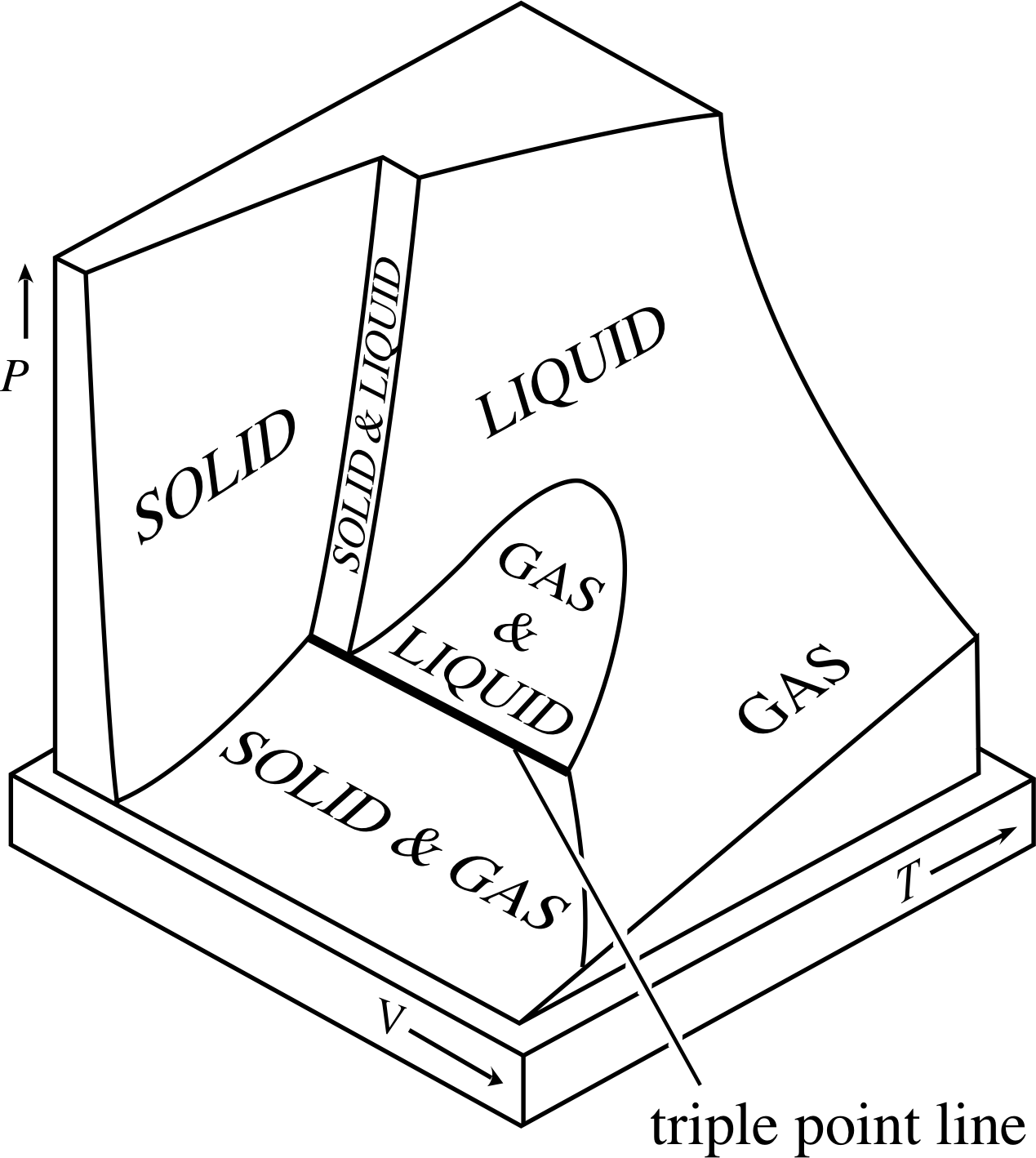
Figure 3 The equilibrium (PVT) surface of a typical substance that contracts on freezing. (Water is an ‘atypical’ substance in this sense because it expands upon freezing.) Notice that there are some very specific conditions, indicated by points on the triple point line, under which the gas, liquid and solid phases of the substance can coexist in equilibrium.
If you compress a sample of ideal gas all you get is a denser sample of ideal gas. However if you compress a real gas, particularly one that has been cooled to a relatively low temperature, it may well turn into a liquid, and if you continue the compression it may even become a solid. These different forms of matter – gas, liquid and solid – are said to be different phases of matter, and the processes that allow one phase to become another – such as the condensation of a gas, or the freezing of a liquid – are said to be changes of phase or phase transitions. The fact that a typical substance can exist as a solid, a liquid or a gas inevitably makes its equilibrium (PVT) surface more complicated than that of an ideal gas.
The equilibrium surface of a fixed quantity of a typical substance is shown in Figure 3. As you can see, when the temperature and volume are large the substance is a gas, but when they are low it is a solid. The liquid phase occurs under intermediate conditions and is distinctly separated from the solid phase, but not from the gas phase, so the distinction between a gas and a liquid is not always clear. Changes of phase, such as freezing and condensation, occur when the temperature, pressure and/or volume of the system are altered in such a way that the state of the system crosses one of the regions in which two different phases coexist.
Even the wide variety of real substances, typical or atypical, does not exhaust the range of systems that can be studied using thermodynamics. Working physicists are almost as likely to use it to study the behaviour of a cavity filled with light (as you will see in Subsection 4.3) as that of a cylinder filled with gas.
Question T3
Imagine that you have a sturdy transparent cylinder filled with the sort of typical substance whose PVT surface is shown in Figure 3. Initially, half the cylinder is occupied by liquid and the other half by gas and the whole system is in equilibrium. Now suppose you gradually reduce the volume of the cylinder (possibly by operating a piston) while taking steps to ensure that the temperature is held constant (possibly by immersing the cylinder in a bath of water at the appropriate fixed temperature). Describe the path on the PVT surface that corresponds to this process, and describe what you would expect to observe as the volume of the cylinder became smaller and smaller.
Answer T3
As the volume is gradually reduced while the temperature is held constant, the state of the system will move across the equilibrium surface following a path parallel to the V–axis. Since the initial state is one in which gas and liquid coexist the path will start inside the ‘GAS & LIQUID’ region of the equilibrium surface, cross the ‘LIQUID’ and ‘SOLID & LIQUID’ regions, and then enter the ‘SOLID’ region.
The observed behaviour would be the following: at first the reduction of volume would cause the proportion of gas to decrease and that of liquid to increase. When all of the gas had condensed, the cylinder would be entirely filled with liquid, the pressure of which would increase as its volume was further reduced. Eventually (at high pressure) part of the cylinder’s contents would become solid. The solid would be denser than the liquid, so it would sink to the bottom of the liquid that still filled the rest of the cylinder. Continued volume reduction would ultimately convert the entire contents of the cylinder to solid which could be further compressed, but usually only with very great difficulty.
3 Heat, work and internal energy
In this section we will define and explore the relationship between heat, work and internal energy. This will enable us to write down the first law of thermodynamics.
3.1 An elementary problem
Imagine using a bicycle pump to pump up a tyre. After pumping for a few minutes, the end of the pump where gas is being compressed will become quite warm. The temperature of the air in that part of the pump is raised each time the pump is operated and the thermal contact that exists between the warm gas and the metal of the pump allows the pump itself to become warm as a result of the pumping action.
✦ How could you achieve the same temperature rise in the pump without pumping?
✧ By bringing the pump into thermal contact with another body at a higher temperature. For example you could briefly immerse the end of the pump in hot water.
No prizes for getting the answer right – it was a very straightforward question. Here is something equally easy, but with wide ranging implications.
✦ If you were handed a bicycle pump and the compression end was slightly warm, would you be able to tell if the temperature rise was due to immersion in hot water or due to pumping up a tyre?
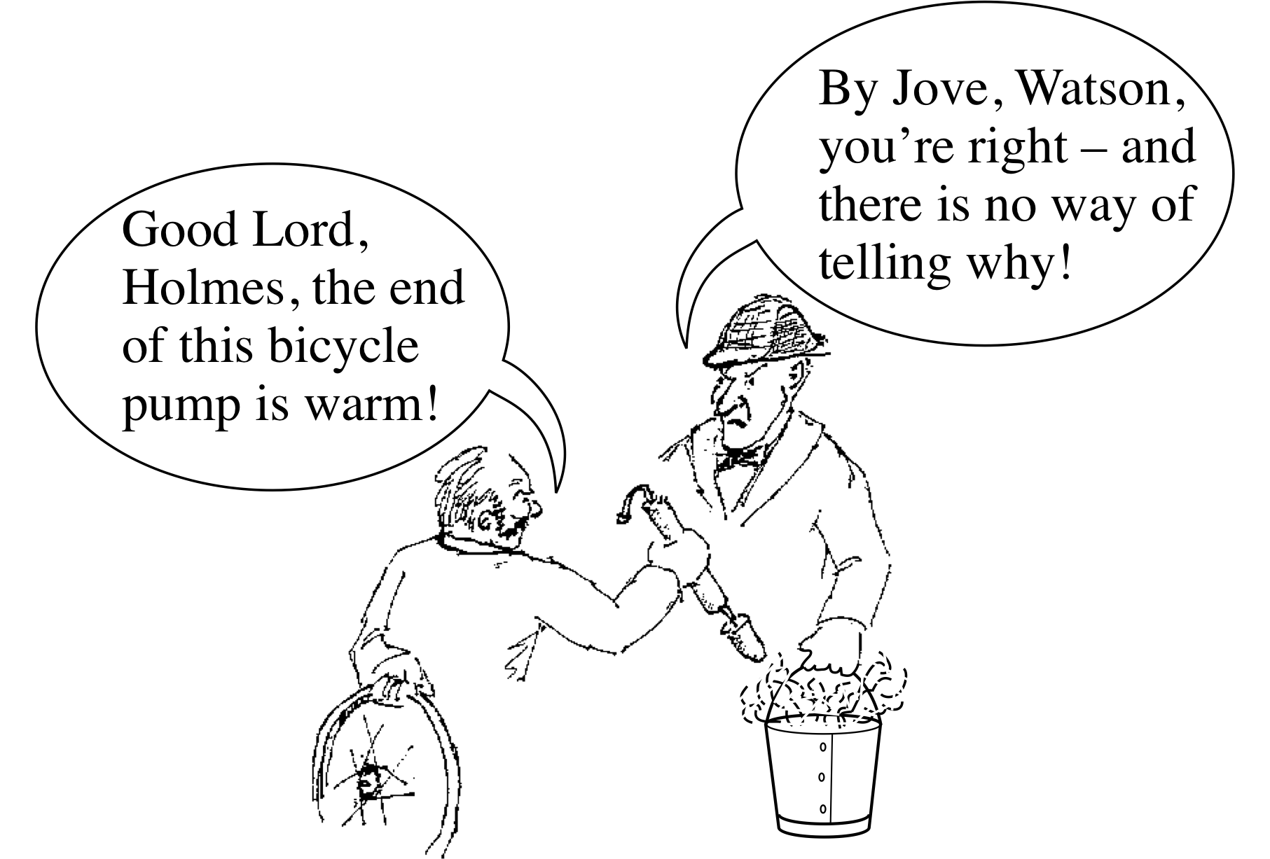
Figure 4 There is no difference between a temperature rise caused by doing mechanical work on a system and one caused by directly heating it.
✧ No; assuming that the pump is in an equilibrium state, the two effects are indistinguishable! There is no way to tell whether the increase in temperature of the air in the pump was caused by direct heating (as in immersion in hot water) or by doing mechanical work (as in pumping up a tyre) or by some combination of both. Of course we are ignoring circumstantial evidence such as the end of the pump being wet or finding that the pump is attached to a fully inflated tyre (see Figure 4).
We are more interested in the possibility or impossibility of distinguishing between the processes in principle.
This point being made here is really the same point that was made at the end of Subsection 2.2. Temperature is a function of state, so its value depends only on the equilibrium state of the system, and not on how that state was attained. The system has no ‘memory’ of how it arrived at any particular equilibrium state. It may appear that a lot of fuss is being made over a rather simple point, but the equivalence (in the above sense) of directly heating a system or doing mechanical work on a system lies at the heart of the first law of thermodynamics.
3.2 Internal energy
We can gain more insight into the ‘curious’ behaviour of the bicycle pump by thinking in terms of energy rather than temperature.
The pump as a whole can have potential energy by virtue of its gravitational interaction with the Earth, and kinetic energy by virtue of its motion. However, in addition to these two contributions, its total energy will also contain a contribution arising from the atoms of which the pump is composed. Even when the pump as a whole is stationary, these atoms have their own microscopic motions which give the pump an internal kinetic energy that is quite distinct from the kinetic energy of its overall motion. Similarly, the electrical interactions between the atoms of the pump also give it an internal potential energy that can be distinguished from the gravitational potential energy associated with its overall position. The sum of these internal kinetic and potential energies, and any other internal energies that might exist, comprises the total internal energy of the pump. i
Internal energy plays an important part in thermodynamics and is related to temperature in an interesting way. As you might expect, when the temperature of a system is raised its internal energy increases. In the case of a fixed quantity of ideal gas confined in a cylinder this relationship is easy to understand; from a microscopic point of view the gas consists of tiny randomly moving particles that are incessantly colliding with one another and with the walls of their container. Raising the temperature of the gas simply corresponds to increasing the average kinetic energy of the particles.
So in this case, the temperature of the gas is a measure of the average internal kinetic energy associated with the random motion of the molecules that make up the gas. In fact, it can be shown that for an ideal gas of simple point like particles the internal energy U is related to the absolute temperature T by the equation:
$U = \dfrac3nRT$ i
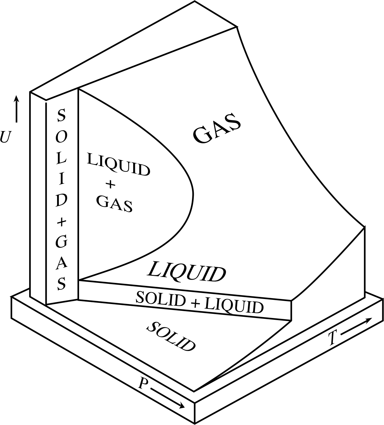
Figure 5 The variation with temperature and pressure of the internal energy U of a fixed quantity of a typical substance. Note that there are vertical regions on the UVT surface (corresponding to changes of phase) in which a change in internal energy is not necessarily accompanied by a change in temperature.
For other systems, such as real gases or the metal of the pump, the situation is broadly similar, but the precise relationship between temperature and internal energy is more complicated. Although it remains true that an increase in temperature corresponds to an increase in internal energy, it is not necessarily the case that an increase in internal energy corresponds to an increase in temperature. For instance, if you take a bucket of ice at a temperature of −10 °C (≈ 263 K) and directly heat it on a stove, you will raise its temperature and increase its internal energy. At least, that is what you will do until the temperature reaches 0 °C and the ice starts to melt. Once melting commences, continued heating will still increase the internal energy of the contents of the bucket, but it won’t raise the temperature – it will just cause more of the ice to melt. Eventually, when all of the ice has changed its phase to become water (at 0 °C) further increases of internal energy due to heating will once again cause the temperature to rise.
The complicated relationship between temperature and internal energy for a fixed quantity of a typical substance is shown in Figure 5.
The important point about internal energy is that it too is a function of state.i In other words, whenever the system is in an equilibrium state, its internal energy is determined by that equilibrium state and not by the processes that produced it. This explains why the cause of the raised temperature of the pump is bound to be ambiguous, unless we happen to know the detailed history of the pump. The raised pump temperature we observe simply reflects the raised internal energy of the pump. The fact that the internal energy is a function of state means that, in the absence of any additional information, there is no way of telling whether the internal energy was raised by direct heating (e.g. by immersing the pump in hot water) or by doing work (e.g. by pumping up a tyre).
3.3 Heat and work
In the preceding discussion, the terms ‘direct heating’ and ‘doing work’ were used in their everyday sense to indicate two different ways of increasing the internal energy of a system. In this subsection we shall give general definitions of heat and work, both of which are important concepts in thermodynamics. Let’s deal with heat first.
If two bodies at different temperatures are brought into thermal contact, the warmer one will be cooled and the cooler one warmed. If the two bodies are thermally isolated from the rest of the universe, they will end up at the same temperature. Everyone would agree that this process involves the flow of heat from one body to the other, but what exactly is heat, and how does it influence temperature?
Two hundred years ago, some scientists would have said that heat was a substance, sometimes called caloric. They would have explained the behaviour of bodies in thermal contact like this:
‘All bodies contain a fluid called caloric. Caloric flows from high temperature to low temperature and if you increase the caloric in a body its temperature will rise.’

Figure 6 Count Rumford’s experiment.
Not all would have agreed. Experiments performed by Benjamin Thompson (1753–1814) (who later became Count Rumford of Bavaria) indicated that the caloric theory was incorrect. While working in Bavaria, Rumford studied the production of cannons (Figure 6) which were cooled by water while they were being bored. Rumford observed that more water was boiled away when the boring tool was blunt – a fact which could not be explained by caloric being squeezed out of the cannon into the water. Rumford’s alternative explanation was that the heating effect was caused by the motion of the borer itself. Later, the British scientist James Prescott Joule (1818–1889) refined these experiments and showed that there was an equivalence between heating and mechanical work. A given amount of work, performed in the course of stirring a liquid or rubbing a body or in some other appropriate way, had a fixed heating effect. This discovery paved the way for the eventual realization, by William Thomson (1824–1907) (who later became Lord Kelvin) and others, that direct heating and the performance of mechanical work were alternative methods of transferring energy to a system.
Armed with this insight into the importance of energy we would now describe the flow of heat in the following way;
‘All bodies contain internal energy. When two bodies with different temperatures are placed in thermal contact, energy is transferred from the body with the higher temperature to the body with the lower temperature. This net transfer of energy continues, altering the internal energies of the two bodies, until they attain the same temperature.’
What exactly is heat itself? It is notoriously difficult to clear away the clutter of history that surrounds this topic, but the conventional modern answer to the question is the following:
Heat is energy which is transferred between a system and its environment as a direct result of temperature differences between them. The direction of heat flow is from high temperature to low temperature.
There are several points that should be noted about this highly restrictive definition of heat. First, you should notice that heating is not necessarily due to heat. We often say that a body has been ‘heated’ whenever we find that its temperature has been raised; but as you have seen, this might be due to energy that has been transferred from a hotter body (i.e. heat), or it might be the result of work being done e.g. stirring, rubbing etc.
Second, notice that the energy which is transferred as heat is not identified as some particular form of energy, it is simply energy. This means that once some heat has been absorbed into the internal energy of a body there is no way of distinguishing it from any of the other energy that makes up the total internal energy of the body. It is therefore not generally meaningful to speak about the ‘heat content’ of a body. Although physicists are well aware of this, it is still common practice to refer to the internal kinetic energy of a body as its ‘heat energy.’ Even more confusingly, when bodies collide it is not uncommon for them to do work on each other, with the consequence that the internal energy of each is increased and its temperature rises. In such circumstances it is quite normal to hear a physicist say that some of the kinetic energy involved in the collision has been dissipated as heat, even though the bodies may not have been at different temperatures throughout the process. These departures from modern terminology are not usually of much concern, but if you want to know whether heat (in the modern sense) has really been transferred in any particular process, just ask yourself if bodies with different temperatures were in thermal contact during the process.
If the only transfer of energy between a system and its environment is that due to temperature difference, then the increase in internal energy of the system ∆U must be equal to the heat Q transferred to it so,
∆U = Q(2)
The sign convention adopted in Equation 2 implies that heat flowing to a system is positive. Heat flowing from a system will therefore be negative and will decrease the internal energy of the system. i
Having defined heat, we can now lump together all other forms of energy transfer and give them the name of ‘work’.
Work is energy transferred between a system and its environment by any process in which a temperature difference is not directly involved.
Note that this definition of work is much more general than the definition of work used in mechanics, where it is essentially the (scalar) product of a force and a displacement in the direction of the force. However, the mechanical definition of work is fully consistent with the thermodynamic definition, and can be used to quantify the work done in certain situations as we shall now show.
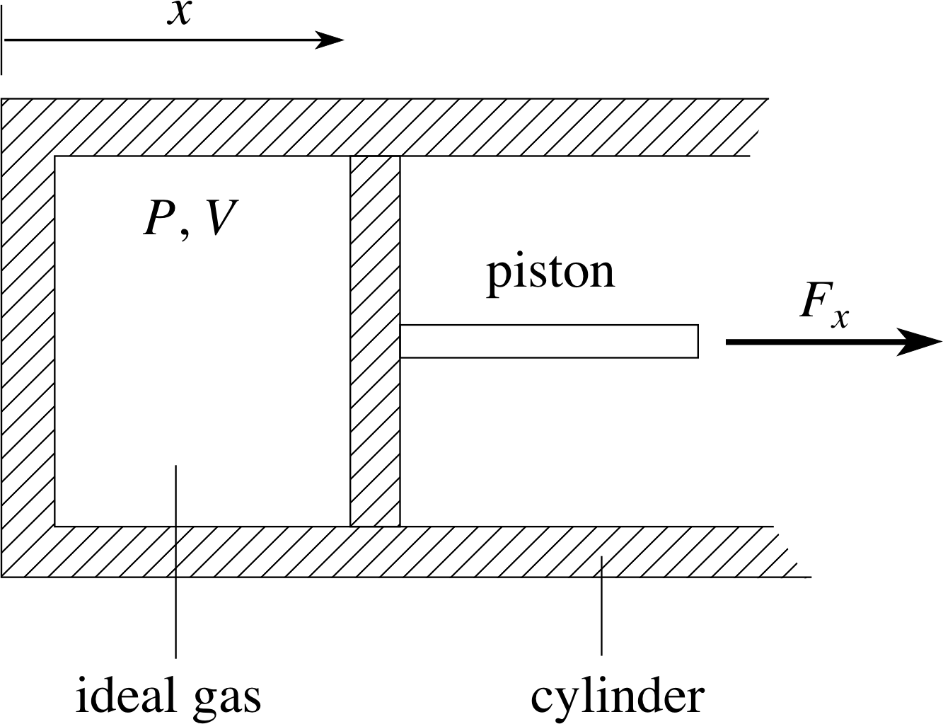
Figure 7 A thermally insulating cylinder of cross–sectional area A containing a fixed quantity of gas which exerts a force Fx on the piston.
Consider the system shown in Figure 7; a cylinder of internal length x and cross–sectional area A, containing a fixed quantity of ideal gas at pressure P and temperature T. One of the end walls of the cylinder is a piston which will be subject to a force Fx = PA due to the pressure of the gas.
Initially we will assume the system is in equilibrium with pressure Pa and volume Va. This means that there must be some external agency (some part of the environment) that is balancing the force Fx exerted by the gas and preventing the piston from moving. We shall not be concerned with the details of that external force, but it should be kept it in mind since it is vital for the equilibrium of the system. Since the quantity of gas is fixed, the pressure and volume are sufficient to specify the equilibrium state of the gas as described in Section 2. The temperature, density and other bulk properties can be easily calculated.
Now suppose that the external force preventing the piston from moving is relaxed a little, so that the gas expands quasistatically until it arrives at another equilibrium state with pressure Pb and volume Vb. The force that the gas exerts on the piston will have done some mechanical work during this expansion and will have transferred some energy to the environment; we call this the work done by the gas on the environment. How much work will be done by the gas in the given expansion?
A constant force Fx acting in the x–direction and moving an object (such as the piston) through a small distance ∆x does a small amount of work given by:
∆W = Fx ∆x
In the case of the gas filled cylinder we know that Fx = PA, so we can write ∆W = PA∆x, but we also know that the product A∆x is equal to the change in volume of the gas ∆V so:
∆W = PA∆x = P∆V
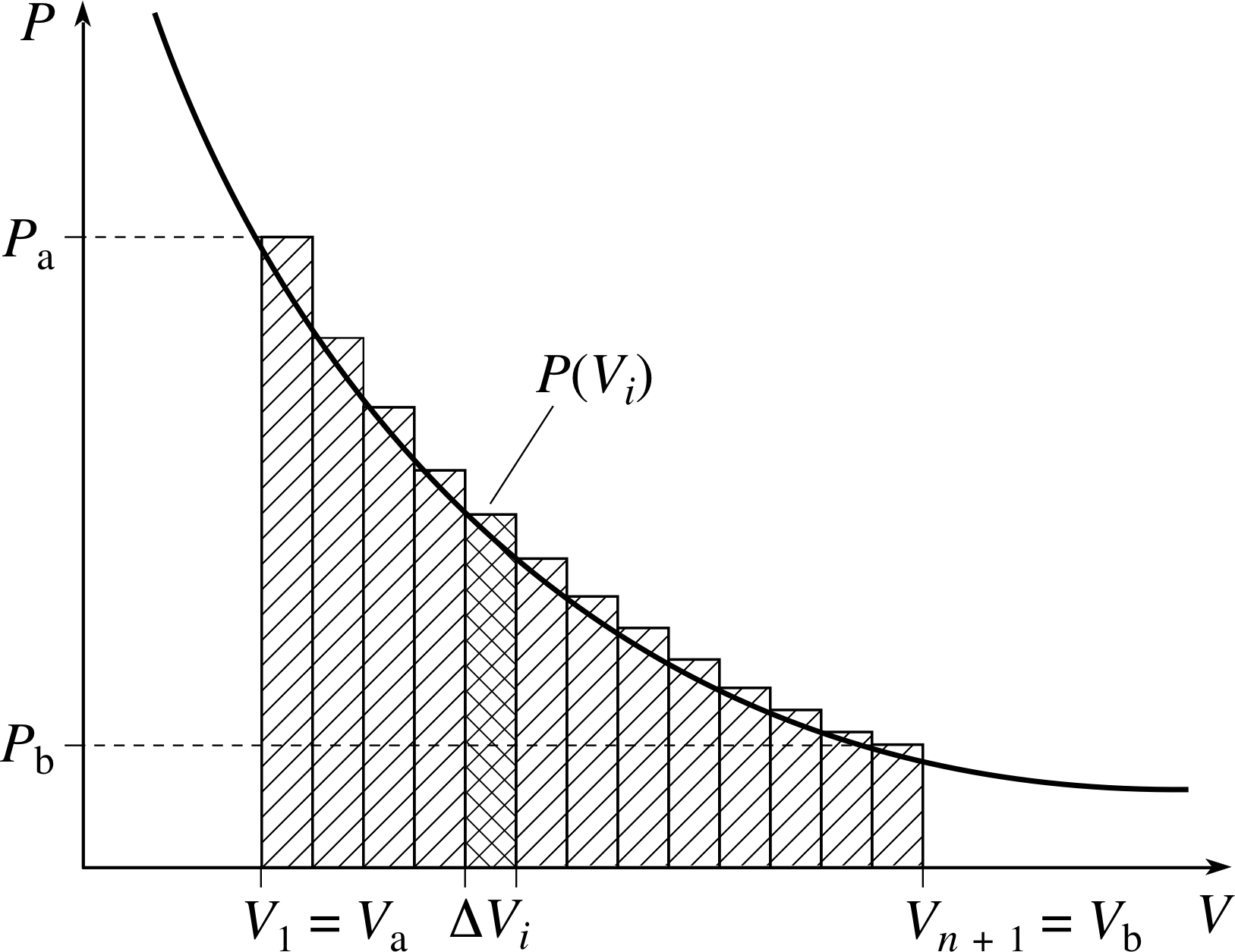
Figure 8 A visualization of Equations 3 and 4.
As the gas expands its pressure may fall, so the force Fx = PA that concerns us may not be constant. Nonetheless, we can still use the expression ∆W = P∆V to find the approximate amount of work done over a sufficiently small expansion. This means we can find an approximate expression for the total work done by the gas as its volume increases from V a to V b by dividing the total change of volume into many small volume increments and summing up the work done in each of those small increments (See Figure 8). Adopting this approach we see that the total work done by the thermally isolated gas is approximately:
W ≈ P (V1)∆V1 + P (V2)∆V2 + P (V3)∆V3 + ... + P (Vn)∆Vn
i.e.$\displaystyle W \approx \sum_{i=1}^n P(V_i)\Delta V_i$
where V1 = Va, Vn + 1 = Vb, and P (Vi) represents the pressure in the gas at the start of the ith small volume increase.
We can get a more accurate expression for the work done by reducing the size of the largest step, and letting the number of steps correspondingly increase. In fact, in the limit as the largest step becomes vanishingly small this sum yields the exact value of W, so we may write:
$\displaystyle W = \lim_{\Delta V\to 0}\left(\sum_{i=1}^n P(V_i)\Delta V_i\right)$(3)
A limit of a sum of this kind is generally referred to as a definite integral, and is written as follows:
$\displaystyle W = \int_{V_{\rm a}}^{V_{\rm b}}P(V)\,dV$(4)
where P (V) now represents the pressure of the gas when its volume is V. The steps leading to Equation 4 are explained in greater detail in the block of modules devoted to integration in the maths strand of FLAP, but if you are not already familiar with the techniques of integration you will probably find it easier to think of the process in graphical terms. In this case the smooth curve of Figure 8 shows the variation of the pressure P with the volume V for the process we are considering.
The work done in any small part of the expansion from Vi to Vi+1 is approximately represented by the area of the corresponding rectangular strip, P (Vi)∆Vi. The total amount of work done in expanding from Va to Vb is approximately represented by the sum of the areas of all the rectangles. As the number of rectangles increases and they become narrower, their total area approaches the area under the smooth curve between Va and Vb. The area under the curve between Va and Vb, measured in the scale units appropriate to the graph, may therefore be said to equal the definite integral of P (V) from Va to Vb.
In order to use Equation 4, or the equivalent graph, to evaluate the work done in any particular process we need to know the precise relationship between P and V at every stage of that process. Remember, any quasistatic process corresponds to a particular pathway on the PVT surface and therefore implies a particular relationship between P and V.
Figure 7 A thermally insulating cylinder of cross–sectional area A containing a fixed quantity of gas which exerts a force Fx on the piston.
For the sake of definiteness, let us suppose that the cylinder in Figure 7 is thermally isolated from its environment so that no heat can flow in or out of the cylinder during the process. A process of this kind is called an adiabatic process. We shall not pause to prove it here, but it can be shown that during an adiabatic process a fixed quantity of ideal gas satisfies an equation of the form:
P = BV−γ
where γ is a constant determined by the nature of the gas, and B is a constant that characterizes the isothermal process. i It should be noted that the gas satisfies this adiabatic condition as well as the ideal gas equation of state (PV = nRT). Given a value for γ, the initial state of the process will determine the value of B, and the adiabatic condition will then determine those equilibrium states which can be reached by an adiabatic process starting from the given initial state.
Using the adiabatic relation between P and V, we see from Equation 4 that the work done in an adiabatic process in which the volume changes from Va to Vb is
$\displaystyle W = \int_{V_{\rm a}}^{V_{\rm b}}BV)^{-\gamma}\,dV = \left[\dfrac{BV^{1-\gamma}}{1-\gamma}\right]_{V_{\rm a}}^{V_{\rm b}} = \dfrac{B\left(V_b^{1-\gamma}-V_a^{1-\gamma}\right)}{1-\gamma}$ i
✦ For an ideal gas of structureless point particles, B is positive and γ = 5/3. Under these circumstances what can you say about the relative sizes of Va and Vb if W is to be negative? Does your answer make physical sense?
✧ Since γ > 1, it follows that 1 − γ < 0. Therefore W will be negative whenever Vb1−γ − Va1−γ is positive, i.e. when Vb < Va. So, the work W done by the gas will be negative when the gas is compressed; which makes good physical sense. It’s important to remember that W is an algebraic quantity that may be positive or negative.
Question T4
Fifty moles of an ideal gas, for which γ = 5/3, have volume Va = 1.00 m3 and pressure Pa = 1.00 × 10⁵ Pa. After an adiabatic process its volume has increased to Vb = 2.00 m3. What is the final pressure of the gas? What was the initial temperature of the gas, and what is its final temperature? Show that this particular adiabatic process is characterized by B = 1.00 × 10⁵ N m3, and hence determine how much work is done by the expanding gas.
Answer T4
It follows from the adiabatic condition, P = BV−γ, that PVγ = constant. Thus PaVaγ = PbVbγ
In this case 1.00 × 1052 Pa × (1.00 m3)5/3 = Pb(2.00 m3)5/3
so$P_{\rm b} = \rm \dfrac{1.00\times10^5}{(2.00)^{5/3}}\,Pa = 3.15\times10^4\,Pa$
Using the equation of state, the initial temperature will be:
$T_{\rm a} = \dfrac{P_{\rm a}V_{\rm a}}{nR} = \rm \dfrac{1. 00\times10^5\times1.00}{50\times8.31}\,K = 241\,K$
and the final temperature will be:
$T_{\rm b} = \dfrac{P_{\rm b}V_{\rm b}}{nR} = \rm \dfrac{3.15\times10^4\times2.00}{50\times8.31}\,K = 152\,K$
Throughout this particular adiabatic expansion B = PaVaγ = 1.00 × 10⁵ N m2. The work done in the adiabatic expansion is therefore:
$W = \rm \dfrac{1.00\times10^5\left[(2.00)^{-2/3}-(1.00)^{-2/3}\right]}{-2/3}\,J = 5.55\times10^4\,J$
Since no heat is exchanged between a system and its environment during an adiabatic process any change in the internal energy of the system must be entirely due to work done by or on the gas. If, as above, we use W to represent the work done by the system during a process, it follows that the change in the internal energy of the system ∆U during an adiabatic process is given by:
∆U = −W(5) i
The sign convention adopted in Equation 5 implies that work done by a system is positive. Work done on a system will therefore be negative and will increase the internal energy of the system. Note that Equation 5 is true of any adiabatic process, not just those involving ideal gases.
Question T5 i
An expression for the internal energy of an ideal gas of point particles was given in Subsection 3.2:
$U = \dfrac32nRT$
Use that expression, together with the temperature values you obtained in answering Question T4 to evaluate the work done in the adiabatic expansion described in Question T4.
Answer T5
According to Subsection 3.2, U = 3nRT/2. It follows that the change in internal energy in a process in which the temperature changes from Ta to Tb is:
$\Delta U = U_{\rm b}-U_{\rm a} = \dfrac32 nR(T_{\rm b}-T_{\rm a})$
i.e.$\Delta U = \rm \dfrac32\times50\times8.31\times(152 - 241)\,J = -5.55\times10^4\,J$
It follows from Equation 5,
∆U = −W(Eqn 5)
that the work done by the gas in an adiabatic expansion is:
W = −∆U = 5.55 × 10⁴ J
This agrees with the value obtained in Answer T4.
The example we have been discussing involved mechanical work – but it is worth remembering that our definition of work includes all processes of energy transfer that do not directly involve a temperature difference. For example connecting a wire (the system) between the terminals of a battery (part of the environment) will cause the wire’s temperature (and hence its internal energy) to rise. If the wire is thermally insulated then Equation 5 still applies but this time W is the (negative) chemical work done on the wire by the battery.
3.4 The first law of thermodynamics
Subsection 3.3 described two methods of increasing the internal energy of a system: transferring heat to it and doing work on it. We deliberately considered processes in which either one method of energy transfer occurred or the other. However, many processes involve both methods.
In the presence of both methods of energy transfer we might expect to find that ∆U = Q − W. As we shall shortly demonstrate, the values of Q and W involved in any particular process depend on the details of that process, but U is a function of state, so the value of ∆U will depend only on the initial and final equilibrium states that mark the beginning and end of the process.
The formal statement that this is so is known as the first law of thermodynamics: i
If a system undergoes a change from one equilibrium state to another, the difference between the heat supplied to the system and the work done by the system will depend only on the initial and final equilibrium states and not on the process by which the change is brought about.
∆U = Q − W(6)
Since heat and work have been defined in such a way that they include all possible methods of transferring energy between a system and its environment, the first law amounts to the assertion that energy is conserved.
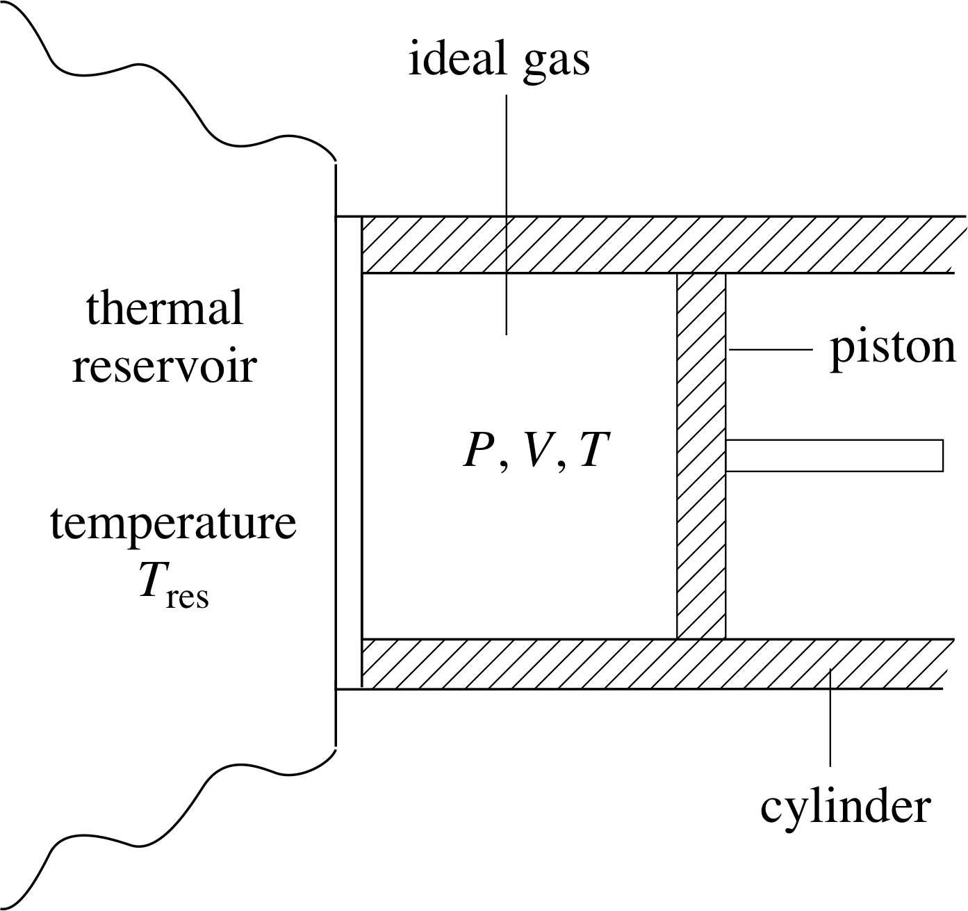
Figure 9 Gas container in thermal contact with a thermal reservoir at temperature Tres.
The internal energy of a system is only changed when energy is transferred to or from that system. In the context of the nineteenth century, the first law highlighted the general importance of energy, an importance that was only beginning to be appreciated around 1850. It also plays an important part in the logical structure of thermodynamics since it implies the existence of a function of state U without any recourse to microscopic arguments about the energies of individual atoms or molecules of the sort we permitted ourselves in Subsection 3.1.
Let’s now use the first law to show that Q is generally not a function of state, thereby demonstrating that the idea that bodies have an identifiable ‘heat content’ must be wrong. Once again we wish to consider a cylinder containing a fixed quantity of ideal gas, and a process in which the equilibrium state of the gas changes from one in which P = Pa and V = Va to one in which P = Pb and V = V b. However, this time, instead of thermally isolating the cylinder, we will allow heat exchange with the environment by arranging for part of the cylinder to be in contact with a thermal reservoir (that is a large body to or from which heat can be transferred without changing its temperature Tres, see Figure 9).
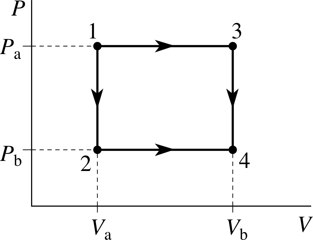
Figure 10 PV diagram showing two different paths between the same initial and final states.
We needn’t worry about how a thermal reservoir might be constructed, but we will suppose that we can adjust its temperature Tres to be any value we desire. That means we can control the flow of heat into or out of the system by setting Tres to be greater or less than the temperature of the gas.
Using this apparatus we can investigate a number of different processes leading from state 1 (defined by Pa and Va) to state 4 (defined by Pb, Vb). Two of these processes are shown in Figure 10, each is a two–step process; the first will be called 1–2–4 and leads from the initial state to the final state via state 2(Pb, Va); the second will be called 1–3–4 and goes from the initial state to the final state via state 3(Pa, Vb). These processes are described in more detail below; neither of them is adiabatic.
| Process 1–2–4 | Process 1–3–4 |
|---|---|
| Step 1 Holding the piston fixed, so that V remains constant at Va, decrease the value of Tres so that heat flows out of the system, its temperature falls and its pressure decreases until it reaches state 2. | Step 1 By suitable adjustments of Tres and movement of the piston, increase the volume while keeping the pressure constant at Pb until the gas reaches state 3.
|
| Step 2 By suitable adjustments of Tres and movement of the piston, increase the volume while keeping the pressure at Pb constant until the gas reaches state 4. |
Step 2 Holding the piston fixed, so that V remains constant at Vb, decrease the value of Tres so that heat flows out of the system, its temperature falls and its pressure decreases until it reaches state 4. |
Question T6
If Pa = 2.00 × 10⁵ N m−2, Pb = 1.00 × 10⁵ N m−2, Va = 1.00 m3 and Vb = 2.00 m3, calculate the work done by the gas in the processes 1–2–4 and 1–3–4 described above.
Answer T6
In process 1–2–4, no work is done in Step 1 because there is no change of volume. The pressure, and hence the force, is constant in Step 2, so the total work done in the process is:
W1-2-4 = Pb(Vb − Va) = 1.00 × 105 Pa × (2.00 − 1.00) m3 = 1.00 × 10⁵ J
In process 1–3–4, no work is done in Step 2, and the pressure is constant in Step 1. Hence the total work done in the process is:
W1-3-4 = Pa(Vb − Va) = 2.00 × 105 Pa × (2.00 − 1.00) m3 = 2.00 × 10⁵ J
The answer to Question T6 shows that the work done by the system in moving between the initial and final equilibrium states depends on the path taken.
Question T7
Can the work done by a system generally be described as a function of state? Can the heat transferred to a system generally be a function of state? Explain your answers, making clear the role of the first law of thermodynamics.
Answer T7
According to the definition of ‘function of state’ in Section 2, a function of state depends only on the equilibrium state of the system and not on how it got there. It follows from Answer T6 that the work done by a system cannot generally be described as a function of state.
The internal energy U is a function of state, so it changes by the same amount in process 1–2–4 as in process 1–3–4. However, according to the first law of thermodynamics ∆U = Q − W. Since processes 1–2–4 and 1–3–4 correspond to identical values of ∆U but different values of W, it follows that the two processes must also correspond to different values of Q. It follows that the heat transferred to a system cannot generally be described as a function of state.
As noted earlier, the fact that internal energy and temperature are functions of state while work and heat are not is the reason why it is impossible to tell whether a temperature rise in a bike pump has been caused by direct heating or by work done on the gas or by a combination of the two.
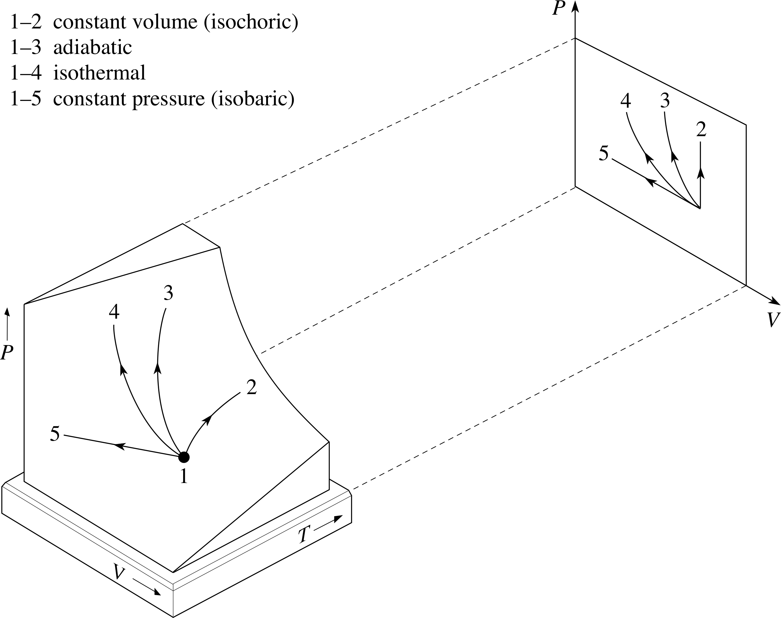
Figure 11 Some simple processes involving an ideal gas, together with their projections on to the PV plane. Note that in each case the initial state of the process determines which other states are accessible by the process concerned. It is not the case that any two states may be directly linked by every kind of process. Remember that isothermal means ‘at constant temperature’ and adiabatic means that there is no transfer of heat.
In Subsection 3.3 we considered an adiabatic process in which no heat flowed in or out of the system, and we saw that in such a process a fixed quantity of ideal gas obeys the condition PVγ = constant. In this subsection we have considered constant volume processes (such as Step 1 of process 1–2–4) and constant pressure processes (such as Step 1 of process 1–3–4).
An example of each of these processes is shown in Figure 11, along with their projections onto the PV plane. Also shown is another kind of process, an isothermal process, in which the temperature remains constant.
All these simple processes play important roles in thermodynamics.
For a fixed quantity of ideal gas, it follows from the equation of state (PV = nRT) that in an isothermal process the gas must obey the condition
PV = D(7)
where D is a constant that characterizes the isothermal process. It should be noted that the gas satisfies this isothermal condition as well as the ideal gas equation of state (PV = nRT). The initial state of the process will determine the value of D, and the isothermal condition will then determine those equilibrium states that are accessible in an isothermal process that starts from the given initial state.
The work done by a fixed sample of ideal gas during an isothermal expansion from Va to Vb is given by:
$\displaystyle W = \int_{V_{\rm a}}^{V_{\rm b}}P\,dV = \int_{V_{\rm a}}^{V_{\rm b}}\dfrac DV\,dV = D\loge\left(\dfrac{V_{\rm b}}{V_{\rm a}}\right)$ i
✦ Referring to the states used in Question T6,
[Pa = 2.00 × 10⁵ N m−2, Pb = 1.00 × 10⁵ N m−2, Va = 1.00 m3 and Vb = 2.00 m]
confirm that an isothermal process starting from state 1 may pass through state 4.
✧ For state 4 to be isothermally accessible from state 1, both states must satisfy the isothermal condition for the same value of D. Hence we require PaVa = PbVb, which is true for the values given in Question T6.
Question T8
If the gas discussed in Question T6 moves from state 1 to state 4 isothermally, then 1.39 × 10⁵ J of work are done by the gas. Will heat flow into or out of the gas during the process? What will be the quantity of heat involved?
Answer T8
Since the process is isothermal, and the internal energy of an ideal gas is proportional to its temperature, it follows that ∆U = 0 in this case. (This is a special property of the ideal gas; it is not necessarily true of other systems that an isothermal process is one in which ∆U = 0, it wouldn’t be true of a bucket of melting ice for instance.)
Since ∆U = 0 it follows from the first law of thermodynamics that W − Q = 0, so Q = W. But W = 1.39 × 10⁵ J, so Q = 1.39 × 10⁵ J. The fact that Q is a positive quantity in this case means the heat flows into the system.
Question T9
A liquid is irregularly stirred in a well–insulated container and thereby undergoes a rise in temperature. Think of the liquid as the system. (a) Has heat been transferred? (b) Has work been done? (c) What is the sign of ∆U?
Answer T9
There is no heat transfer because there is no temperature difference between the system and its environment. Work has been done on the liquid by the frictional forces exerted by the stirrer as it moves through the fluid. Consequently, Q is zero and W is negative in this case. It follows from the first law of thermodynamics that ∆U = Q − W is positive.
3.5 The first law and the Earth’s atmosphere
Subsection 1.1 mentioned the commonplace observation that atmospheric temperature decreases with height. In fact this holds good up to heights of about 10 km and the average reduction of temperature with height is about 6 K km−1. This phenomenon can at least in part be explained by the first law of thermodynamics. First consider atmospheric pressure.
✦ How and why does atmospheric pressure change with height?

Figure 12a The magnitudes and directions of the forces acting on a block of air in equilibrium with its surroundings. The force due to the pressure difference between the top and bottom surfaces just balances its weight.
✧ If the atmosphere is in mechanical equilibrium (by which we mean that there is no bulk movement of the air, i.e. no air currents in any direction), then the net force acting on any volume of air must be zero.
Consider the block of air shown in Figure 12a. This block has mass m and consequently a weight of magnitude mg acting downwards.
If it is in equilibrium there must be a force of equal magnitude opposing the weight; this force is provided by the pressure difference between the top and bottom of the block. If we mentally divide the atmosphere up into many such blocks then in each block the pressure must be greater at its base than at its top. Therefore the pressure must decrease with height.
✦ In the light of the preceding statement, how would you expect the density to change with height?

Figure 12b Two blocks of air with identical masses. The lower block has a smaller volume.
✧ Imagine two blocks of air with identical masses one above the other as in Figure 12b.
Ignoring for the moment the effect of any temperature difference between the blocks, if the lower block has a higher pressure, it will occupy a smaller volume and hence have a higher density. So density also decreases with height. Of course, as we are in the process of demonstrating, there will be a difference in temperature – but this isn’t enough to compensate for the pressure change. Mountaineers are certainly aware of the change of density with height. At a height of several thousand metres air density is so low that it is difficult to get sufficient oxygen into the lungs to keep the body functioning properly.
Now consider what happens if a body of air is forced to rise because of a mountain. As it rises it expands because of the reduced pressure from the surrounding air acting on it. In thermodynamic terms, it is doing a positive amount of work W on its environment. As air is a poor conductor of heat (see Section 4), we may assume that there is negligible heat exchange with the surrounding air, so the expansion is adiabatic. Consequently Q = 0 and, from the first law of thermodynamics,
∆U = −W
Since W is positive, ∆U is negative and thus the internal energy will decrease and the temperature will fall.
We have described the decrease in temperature with height for a single, imaginary block of air. In reality most of the air in the bottom 10 km of the atmosphere is continually rising and falling mainly due to convection (see Section 4) and the effects of mountain ranges. If the air was dry this would result in an overall temperature variation with height exactly corresponding to that of a rising, adiabatically expanding, block of air (about 10 K km−1). In fact the actual value is about 6 K km−1 due mainly to the effect of the condensation of water vapour. This is the kind of cooling which you might expect to observe on the cycle tour described in Subsection 1.1.
3.6 Summary of Section 3
- 1
-
Internal energy U is the sum of the potential and kinetic energies associated with the constituent molecules of a system.
- 2
-
Heat is energy transferred between a system and its environment as a result of the temperature difference between them. Heat always flows from high temperature to low temperature.
- 3
-
Work is the energy transferred between a system and its environment by any process in which a temperature difference is not directly involved.
- 4
-
Internal energy is a function of state. Heat and work are not functions of state.
- 5
-
The first law of thermodynamics states that, if a system undergoes a change from one equilibrium state to another, the difference between the heat Q supplied to the system and the work W done by the system will depend only on the initial and final states and not on the process by which this change is brought about. This provides a thermodynamic justification for introducing the internal energy as a function of state U such that:
∆U = Q − W
- 6
-
An adiabatic process is one in which there is no heat exchange between the system concerned and its environment. An isothermal process is one in which there is no change of temperature.
- 7
-
The reduction of temperature with height in the bottom few kilometres of the atmosphere can be at least partially explained as the result of adiabatic expansion.
4 Methods of heat transfer
In Section 3 heat was defined as energy transferred because of temperature difference. In this section we will explore three different mechanisms by which the transfer of heat is effected. They are conduction, convection and radiation.
4.1 Conduction
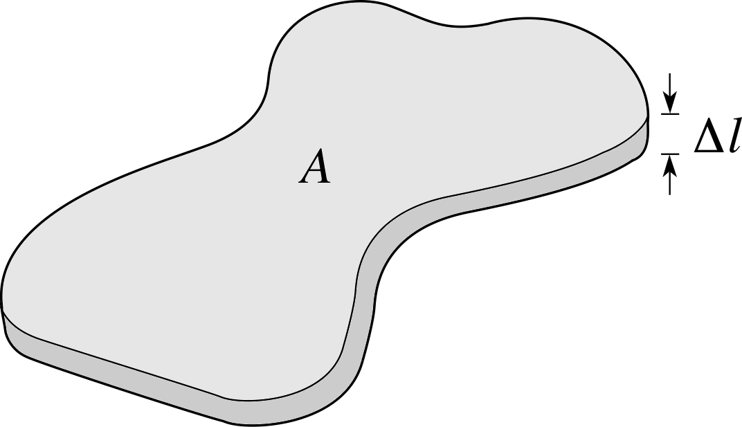
Figure 13 A slab of solid with cross–sectional area A and thickness ∆l.
Perhaps the simplest mode of heat transfer is conduction_of_heatconduction. It can occur in all three phases of matter: solids, liquids and gases. To fix our ideas we think first of a thin slab of solid shown in Figure 13 with thickness ∆l, cross–sectional area A and a temperature difference between its flat faces of ∆T. We can assume that ∆l is so small that heat transfer out of the slab through the sides is negligible. If we imagine a quantity of heat ∆Q flows through the slab in the small time interval ∆t, then the rate of flow of heat can be written as $\dfrac{\Delta Q}{\Delta t}$. It is found experimentally that $\dfrac{\Delta Q}{\Delta t}$is proportional to the temperature gradient $\dfrac{\Delta T}{\Delta l}$and the cross–sectional area A.
Thus$\dfrac{\Delta Q}{\Delta t} \propto A\dfrac{\Delta T}{\Delta l}$
or$\dfrac{\Delta Q}{\Delta t} = -\kappa A\dfrac{\Delta T}{\Delta l}$
where κ (the Greek letter kappa) is a constant called the thermal conductivity coefficient i that is characteristic of the material of the slab. The negative sign indicates that the direction of heat flow is in the opposite direction to the temperature gradient. That is, it flows from hot to cold. In the limit as ∆l and ∆t approach zero, the equation can be written using derivatives, as
$\dfrac{dQ}{dt} = -\kappa A\dfrac{dT}{dl}$(8)
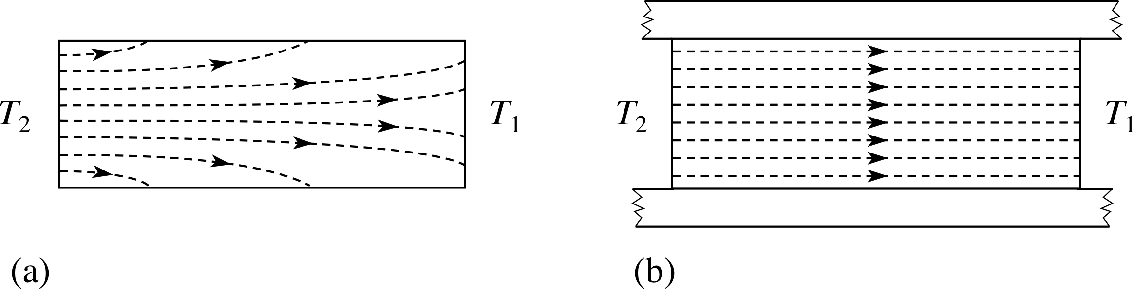
Figure 14 (a) Heat flow along a bar between temperatures T2 and T1 where T2 >T1. The bar is not insulated and some of the heat flow is through the sides of the bar into the environment. (b) The same situation but with a well–lagged bar. Heat flow lines are parallel along the bar so the flow can be said to be one-dimensional.
Equation 8 is known as Fourier’s law and it can be applied to practical problems such as heat flow through walls or along bars. i Often the calculations are complicated by the fact that κ varies with temperature and the heat flow is three-dimensional, but we will only consider simple examples where the flow is one-dimensional.
Such a situation is shown in Figure 14.
If in addition a steady state has been reached so that there is no change of temperature with time at any point in the bar, a simplified form of Equation 8 can be used:
$\dfrac Qt = -\kappa A\dfrac{T_2-T_1}{l}$ (in the absence of convection)(9)
where l is the length of the bar, and Q is the heat that flows in time t.
Question T10
If a copper kettle has a base of thickness of 2.0 mm and area 3.0 × 10⁻² m2, estimate the steady difference in temperature between inner and outer surfaces of the base which must be maintained to enable enough heat to pass through so that the temperature of 1.00 kg of water rises at the rate 0.25 K s−1.
Note that κ (copper) = 390 W m−1 K−1 and the amount of heat required to increase the temperature of 1 kg of water by 1 K is 4.19 × 10³ J.
Answer T10
Rearranging Equation 9,
$\kappa = -\dfrac Qt\times\dfrac1A\times\dfrac{l}{\Delta T}$ (in the absence of convection)(Eqn 9)
$T_2-T_1 = -\dfrac Qt\times\dfrac{l}{\kappa A}$
Here T1 refers to the temperature of the outer surface of the base, T2 is the inner surface temperature.
In this case:
$\dfrac Qt = \rm \dfrac{4.19\times10^3\times1.00\times0.25}{1.00}\,J\,s^{-1} = 1050\,W$
so$T_2-T_1 = \rm -\dfrac{1050\times2.0\times10^{-3}}{390\times3.0\times10^{-2}}\,K = -0.18\,K$
The negative sign makes T1 > T2 as common sense dictates. This emphasizes the fact that copper is a very good conductor of heat. Only a small temperature gradient is needed to transfer heat at a rate of 1 kW.
Question T11
A windowless room 3.0 m high and with a 6.0 m × 6.0 m floor area is insulated with a 10 cm layer of glass-wool. The inside walls and ceiling are to be maintained at 20 °C when the outside surface temperature is 0 °C. What rate of heating must be supplied to the room in order to maintain the desired temperature?
(You should assume that the glass wool with thermal conductivity 0.038 W m−1K−1 is entirely responsible for the insulation and that there is no heat loss through the floor.)
Answer T11
Using Equation 8 (or 9),
$\dfrac{dQ}{dt} = -\kappa A\dfrac{dT}{dl}$(Eqn 8)
$\kappa = -\dfrac Qt\times\dfrac1A\times\dfrac{l}{\Delta T}$ (in the absence of convection)(Eqn 9)
$\dfrac{dQ}{dt} = \rm -0. 038\times(4\times6.00\times3.00 + 6.00\times6.00)\times\left(\dfrac{-20}{0.10}\right)\,W = 820\,W$ (to 2 significant figures)
Question T12 i
An ice–box is built of wood 1.75 cm thick, lined with cork 3.00 cm thick. If the temperature of the inner surface of the cork is 0 °C and that of the outer surface of the wood 12 °C, what is the temperature at the interface? (The thermal conductivity of wood is 0.25 W m−1 K−1; the thermal conductivity of cork is 0.05 W m−1K−1).
Answer T12
Let T1 and T2 be the inner and outer surface temperatures and Ti be the temperature of the interface. Using Fourier’s law and noting that, due to conservation of energy, the rate of heat flow through unit area of cork must be the same as the rate of heat flow through unit area of wood:
$-\dfrac1A\dfrac{dQ}{dt} = \dfrac{\kappa_c(T_1-T_i)}{l_c} = \dfrac{\kappa_w(T_i-T_2)}{l_w}$
where subscripts w and c refer to ‘wood’ and ‘cork’. Rearranging gives:
$T_i = \dfrac{T_1\kappa_cl_w + T_2\kappa_wl_c}{(\kappa_cl_w + \kappa_wl_c)} = \rm \dfrac{(273\times0.05\times1.75\times10^{-2}) + (285\times0.25\times3.00\times10^{-2})}{(0.05\times1.75 \times10^{-2}) + (0.25\times3.00\times10^{-2})}\,K = 283.75\,K = 10.75\,°C$
Figure 12a The magnitudes and directions of the forces acting on a block of air in equilibrium with its surroundings. The force due to the pressure difference between the top and bottom surfaces just balances its weight.
4.2 Convection
Consider a fluid initially in mechanical equilibrium so that is there is no bulk movement. Now imagine that a small source of heat is placed somewhere in the fluid. The temperature of the fluid next to the heat source will increase causing expansion and resulting in a decrease in density.
The weight of fluid occupying a given volume is now less but the force due to pressure difference which balanced the original weight of fluid (see Figure 12a) has not changed. Thus there is a net upward force on the less dense fluid. As it rises its place is taken by cooler, denser fluid which will in turn warm, expand and rise. If a mechanism exists whereby the warm, rising fluid transfers heat to some cooler body (a heat sink) then a cyclical process is established so that the fluid circulates and heat is continually transferred from heat source to heat sink. This method of heat transfer is called convection. i
Question T13 i
Can convection occur in the absence of a gravitational force?
Answer T13
No. The transfer of heat depends on vertical fluid motion caused by an imbalance between the weight of a certain volume of fluid and the pressure difference between its top and bottom. In the absence of gravity neither the weight nor the pressure difference will exist – so there will be no fluid motion.
In general convection is a complicated phenomenon, depending sensitively on:
- the shape of the containing vessel,
- whether the convection is forced or free. Free convection implies that the fluid movement is purely in response to the change of density described above. Forced convection implies that the fluid movement is mechanically assisted. Examples of forced convection include the use of a fan in an oven, stirring a cup of tea or a cool breeze across your cheek,
- the directions and magnitudes of the temperature gradient and the gravitational force,
- the viscosity (loosely, the ‘stickiness’) of the fluid.
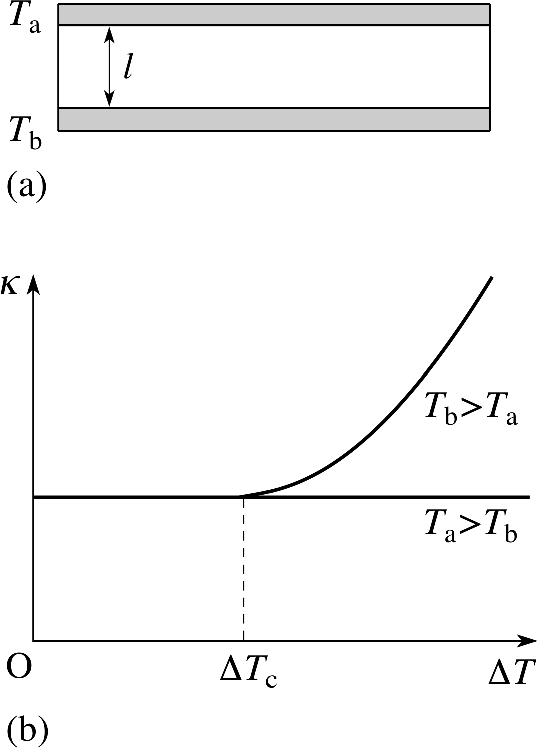
Figure 15 (a) An experiment to investigate convective motion and heat transfer in fluids. The upper and lower surfaces have a common cross–sectional area A. (b) In the absence of convection, heat flow measurements reveal the almost constant value of the coefficient of thermal conductivity with changing values of ∆T. In the presence of convection such measurements reveal a new phenomenon not directly connected with thermal conduction. This is the transfer of heat by convection, and typically results in a rise in the rate of heat transfer with temperature difference above a critical temperature difference ∆Tc. The label κ on the axis is not appropriate in this second case.
There exist a few simple cases which can be analysed in detail. We will briefly mention one.
Consider natural convection between two horizontal plane surfaces of large area A and small separation ($l \ll \sqrt{A}$) as shown in Figure 15a. i
The surfaces above and below the fluid layer are held at temperatures Ta and Tb respectively. If Ta > Tb then no convection can occur and heat transfer will be entirely by conduction. We can thus measure the thermal conductivity κ if we know the rate of heat flow and the dimensions of the fluid.
This is given by rearranging Equation 9,
$\dfrac Qt = -\kappa A\dfrac{T_2-T_1}{l}$ (in the absence of convection)(Eqn 9)
so$\kappa = - \dfrac Qt\times\dfrac1A\times\dfrac{l}{\Delta T}$ (in the absence of convection)
where ∆T = Ta − Tb.
Plotting κ against different values of ∆T should show only small variations as in Figure 15b. If the experiment is repeated with Tb > Ta, so that the heat flow is upwards, something more complicated happens. For small ∆T, the value of −Ql/(tA∆T) is the same as before, but as ∆T increases beyond a certain critical value ∆Tc, the value of this quantity begins to increase (Figure 15b). The changing value of this quantity with ∆T shows that the flow of heat is no longer simply proportional to ∆T.
The critical temperature difference ∆Tc represents the temperature difference at which convection switches on and the results are then roughly consistent with $\dfrac{dQ}{dt}$ proportional to (∆T)5/4 (rather than ∆T) for ∆T > ∆Tc.
The flow pattern in the fluid is also of interest; for this geometry the fluid organizes itself into a regular array of hexagonal cells with fluid moving in one direction along the axis of the hexagons and in the opposite direction along their boundaries. All this complexity from natural convection in a simple geometry! Just imagine how much more complicated it can get. Do not despair! Although it is very difficult to model the intricate details of convection in all but the most simple situations, useful results can often be obtained using a simple empirical formula:
$\dfrac{dQ}{dt} = -hA\Delta T$(10)
where h is called the convective heat transfer coefficient. As you can see, this formula is a little like Fourier’s law in Equation 8,
$\dfrac{dQ}{dt} = -\kappa A\dfrac{dT}{dl}$(Eqn 8)
but it does not contain a length l.
The convective heat transfer coefficient is something which can be looked up in tables or calculated from standard formulae. It depends on shape and orientation, and may also depend on ∆T as in the example shown in Figure 15. From a practical point of view we cannot afford to overlook convection.
Empirical equations such as Equation 10 are useful in appropriate situations, but one should retain a sense of caution about depending too heavily on such calculations in view of the complexity of the phenomenon.
✦ What are the units of h?
✧ Rearranging Equation 10,
$\dfrac{dQ}{dt} = -hA\Delta T$(Eqn 10)
gives$h = -\dfrac{dQ}{dt}\times\dfrac{1}{A\Delta T}$
So the units of h are W m−2 K−1.
Question T14
For natural convection over a flat horizontal plate which is warmer than the surrounding air, the convection coefficient can be calculated from the following empirical formula:
$h = \dfrac{\kappa}{d}\times0.50\times(1.58\times10^8\times d^3\times\Delta T)^{0.25}\,{\rm W\,m^{-2}\,K^{-1}}$
where κ is the conductivity of the air in W m−1 K−1, d is the length of the plate in metres and ∆T is the temperature difference in κ between plate and air. For d = 5 m, calculate h for ∆T = 5 K, 10 K, 15 K. Take κ to be 0.025 W m−1 K−1.
| ∆T/K | h/W m−2 K−1 |
|---|---|
| 5 | 1.4 |
| 10 | 1.7 |
| 15 | 1.8 |
Answer T14
Substituting values in the formula:
Question T15 i
Estimate the heat loss by free convection from a flat roof of dimensions 5 m × 5 m when the temperature difference between the roof and the surrounding air is (a) 5 °C, (b) 10 °C, (c) 15 °C.
[Hint: use the values of h calculated in Question T14.]
Answer T15
| ∆T/K | h/W m−2 K−1 |
|---|---|
| 5 | 1.4 |
| 10 | 1.7 |
| 15 | 1.8 |
(a) Using Equation 10,
$\dfrac{dQ}{dt} = -hA\Delta T$(Eqn 10)
and the values calculated in Question T14, the rate of heat transfer to the atmosphere for ∆T = 5 K is:
$\dfrac{dQ}{dt} = \rm -1.4\times25\times5\,W = -180\,W$ (to 2 significant figures)
(b) For ∆T = 10 K, the same calculation gives:
$\dfrac{dQ}{dt} = \rm -1.7\times25\times10\,W = -430\,W$
(c) For ∆T = 15 K:
$\dfrac{dQ}{dt} = \rm -1.8\times25\times15\,W = -680\,W$
4.3 Electromagnetic radiation and the black–body spectrum
The third process of heat transfer we wish to discuss is commonly called radiation_electromagneticradiation. In the context of heat transfer, this is taken to mean the emission and absorption of electromagnetic radiation.
Electromagnetic radiation is a wave phenomenon, consisting of oscillating electric and magnetic fields and it is something you are in contact with every second of your life. i Light, radio waves, infra–red radiation, ultraviolet radiation, gamma rays and X–rays are all forms of electromagnetic radiation differing only in their wavelength (the distance between successive wave peaks).
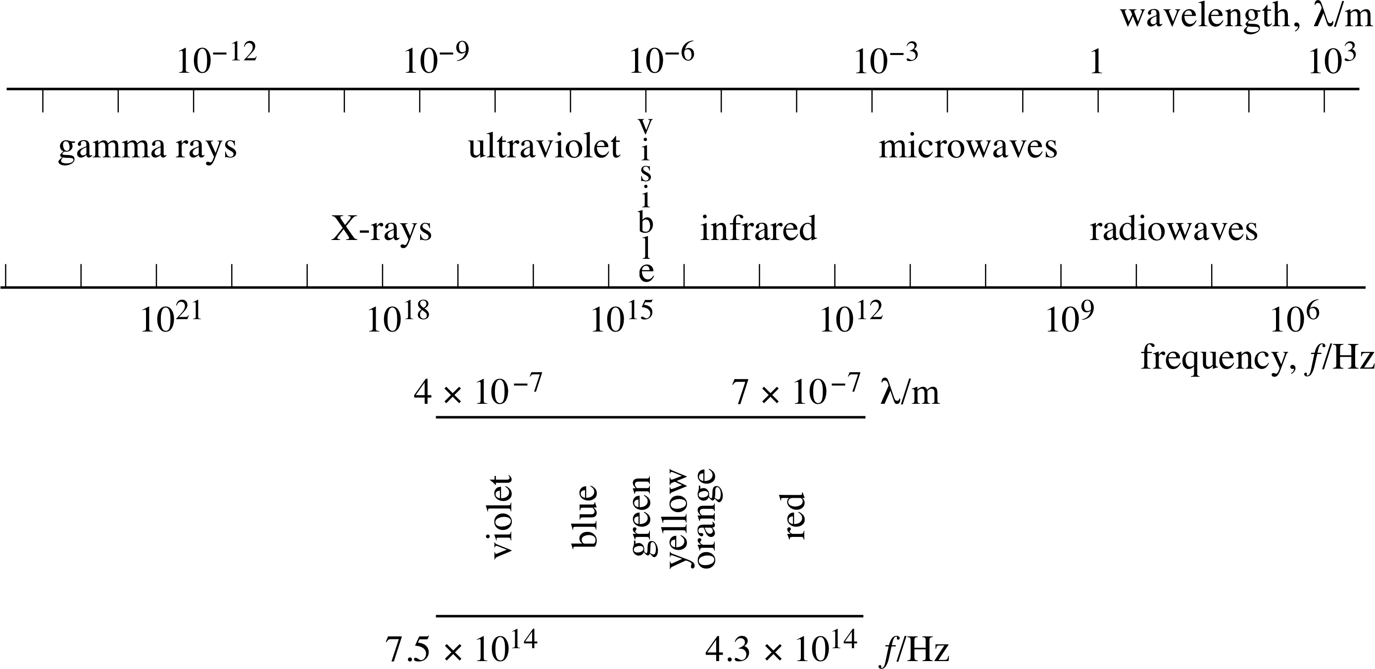
Figure 16 The electromagnetic spectrum.
These different kinds of radiation collectively form the electromagnetic spectrum, as illustrated in Figure 16.
As far as this module is concerned, the important thing about electromagnetic radiation is that it carries energy. All objects emit energy in the form of electromagnetic radiation. i You yourself are radiating energy at about the same rate as a domestic light bulb as you read this module!
The power emitted per unit area of emitting surface is usually carried away by electromagnetic radiation of various wavelengths, so it makes sense to describe the emission in terms of the power radiated per unit area per unit wavelength range. This quantity is called the spectral brightness Rλ i of a surface and generally depends on the temperature and nature of the emitting surface, as well as the wavelength being observed. The spectral brightness of your own body would be greatest at infra–red wavelengths, whereas that of the Sun is greatest at visible wavelengths.
Thermodynamic arguments beyond the scope of this module imply that at a given temperature there is an upper limit to the spectral brightness of a surface at any given wavelength. Any body which produces this maximum spectral brightness at a given wavelength would constitute a perfect emitter at that wavelength and should, according to thermodynamics, also be a perfect absorber of radiation at that wavelength. Consequently, any object which is a perfect emitter at all wavelengths will also be a perfect absorber at all wavelengths. For this reason a perfect emitter of radiation is rather surprisingly known as a black body, though the alternative term full radiator is sometimes used.
Question T16 i
What are the SI units of spectral brightness?
Answer T16
From the definition of spectral brightness, the SI units could be W m−3. However, it is not unusual to see values quoted in units of W m−2 nm−1, emphasizing the per unit wavelength part of the definition.
Question T17 i
If an object appears black, does that mean it is a black body? Does a black body always look black?
Answer T17
An object which appears perfectly black is a perfect absorber (and emitter) in the visible region of the spectrum but it may not be a perfect absorber outside the visible region. Therefore it is not necessarily a black body. A black body will radiate fully (and therefore absorb perfectly) in all regions of the spectrum, so it will be a perfect absorber in the visible region and will not reflect any of the visible radiation that falls upon it. However, if its temperature is sufficiently high it may emit a significant amount of visible light, in which case it won’t look black.
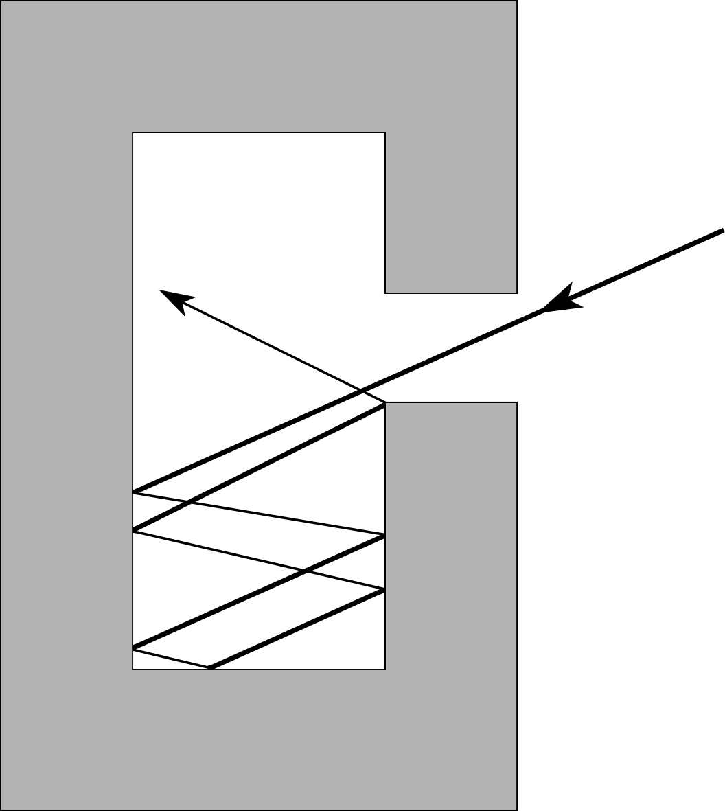
Figure 17 A cavity radiator is a good approximation of a black body because electromagnetic radiation which enters the aperture is absorbed during a series of collisions with the cavity walls.
Exactly how much radiation is emitted by a black body at a given temperature? If we had such an object it would be easy to make measurements. Unfortunately, no real surface emits perfectly at all wavelengths. However a very good approximation can be achieved by forming a cavity with a small aperture in a solid object as shown in Figure 17.
Almost all radiation entering through the aperture will eventually be absorbed somewhere inside the cavity, so the cavity constitutes an (almost) perfect absorber and is therefore a good approximation to a black body. Some of the radiation emitted by the walls of the cavity will inevitably escape through the aperture, and this may be used to study black–body radiation. By adjusting the (uniform) temperature of the cavity’s walls we can investigate how the spectral brightness of a black body varies with temperature as well as wavelength. Such a device is called a cavity radiator. In this situation the hole will always appear brighter than the entire body. This is a direct result of the hole being nearer to a true black body than is the surface of the body. A similar effect is sometimes seen from a cavity within an open fire.
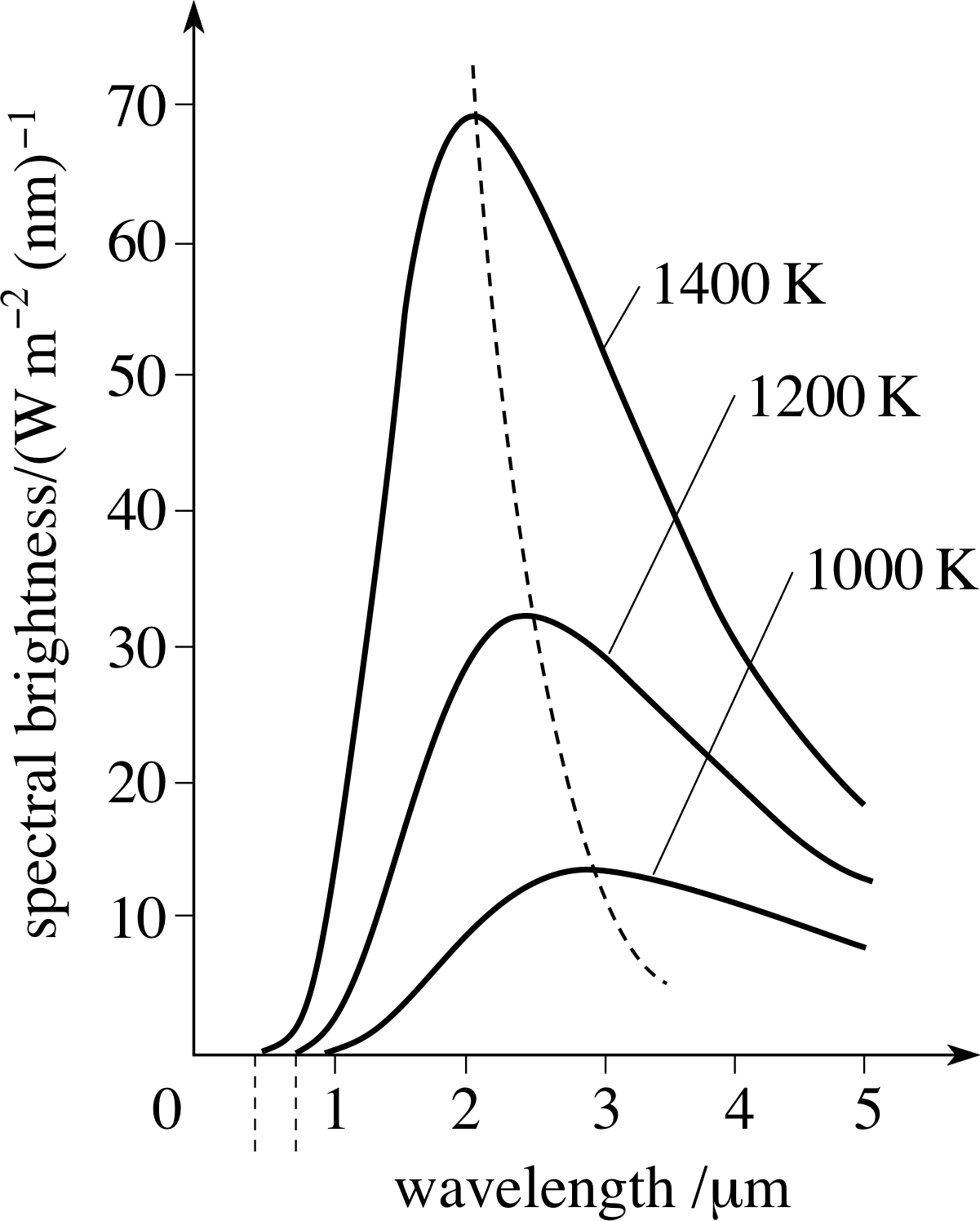
Figure 18 Black–body spectra at various temperatures, shown as plots of spectral brightness against wavelength. The dashed line shows the variation of the spectrum peak with temperature.
The variation of spectral brightness with wavelength for a black body at a given temperature defines the black–body spectrum at that temperature. A sequence of black–body spectra at different temperatures is shown graphically in Figure 18. As you can see, the shape of the spectrum is the same for all temperatures. As the temperature rises, the peak in the curve moves to shorter wavelengths and the total emitted power (represented by the area under the curve) increases. This is in line with everyday observation. A heated object will start to glow dull red as its brightness peak enters the visible region of the spectrum. As its temperature continues to rise it turns orange, yellow and then white as the peak moves to shorter and shorter wavelengths. A very hot star appears blue since its peak emission is in the ultraviolet and it is seen mainly by the light emitted in the blue end of the spectrum.
✦ Show that the total power per unit area emitted by a black body at a particular temperature T is represented by the area under the corresponding black–body spectrum.
✧ The total power emitted per unit area in a narrow wavelength range ∆λ centred on a wavelength λ will be given approximately by Rλ(λ, T) ∆λ, where Rλ(λ, T) is the value of the spectral brightness of the black body at temperature T and wavelength λ. The total power emitted across all wavelengths may be approximated by dividing the whole wavelength axis in Figure 18 into adjacent narrow ranges, finding the power per unit area emitted in each range, and then adding all those contributions together.
As the individual ranges are made smaller and smaller this sum approaches the definite integral:
$\displaystyle \int_0^\infty R_\lambda\,d\lambda$
which represents the area under the graph of Rλ against λ for the appropriate value of T.
The theory of black–body radiation is now well understood. The relationship between Rλ, λ and T for a black body was formulated by Max Planck (1858–1947) in 1900 and is known as Planck’s function. It takes the form
$R_\lambda = \dfrac{c_1}{\lambda^5}\dfrac{1}{\left({\rm e}^{c_2/kT}-1\right)}$(11a) i
where c1 and c2 are constants.
Integrating the Planck function of Equation 11a to find the total power emitted per unit area by a black body across all wavelengths, looks a bit formidable but fortunately the final result can be expressed simply. If R is the total emitted power per unit area, then:
R = σT4(12a)
Equation (12a) is known as Stefan’s law and σ is Stefan’s constant. In SI units σ = 5.67 × 10⁻⁸ W m−2 K−4 i
Question T18
Calculate the power emitted by a hole of area 10 cm2 in the side of a large furnace at a temperature of 3000 K.
Answer T18
The total power emitted by a black body of area A must be AσT4 from Equation 12a,
R = σT4(Eqn 12a)
In this case, power emitted = 10 × 10−4 × 5.67 × 10−8 × 30004 W = 4600 W.
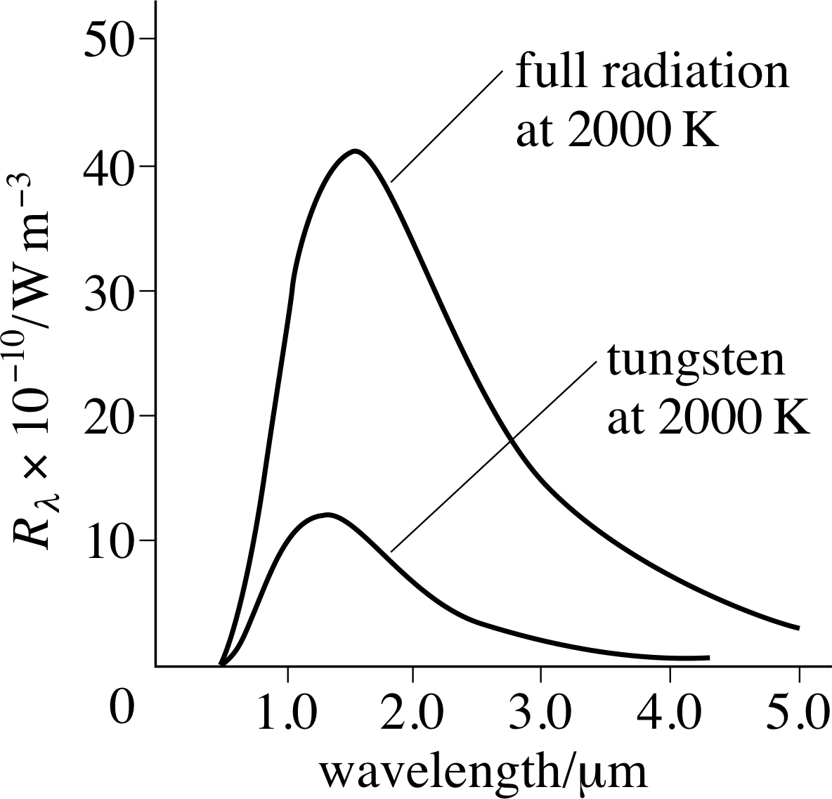
Figure 19 The spectra of tungsten and of a black body at 2000 K. You will sometimes see a black body referred to as a full radiator.
For real objects, the power emitted at a given wavelength is usually less than the black–body spectral brightness. Figure 19 compares the spectrum for tungsten at 2000 K with the black body curve.
Equations 11a and 12a can be adjusted to account for the behaviour of real objects by incorporating a factor known as the emissivity ε (the Greek letter epsilon). Thus Equation 11a becomes
$R_\lambda = \dfrac{c_1}{\lambda^5}\varepsilon_\lambda\dfrac{1}{\left({\rm e}^{c_2/kT}-1\right)}$(11b)
The subscript λ emphasizes the fact that the emissivity may vary with wavelength. ελ is always between 0 and 1.
Equation 12a becomes:
R = εσT4(12b)
where ε is now a representative value of ελ over the whole spectrum and therefore may vary with temperature.
Question T19 i
What is the emissivity of a cavity radiator?
Answer T19
A cavity is a good approximation of a black body, so its emissivity will be close to 1 at all wavelengths.
Question T20 i
If an object has an emissivity of 0.3 at all wavelengths, what fraction of incoming radiation will be absorbed?
Answer T20
By definition 0.3 or 30% of the incoming radiation will be absorbed.
Question T21
The total energy emitted by the Sun in one second is 3.7 × 1026 J. Estimate the average surface temperature of the Sun, assuming it to be a spherical black body with a radius of 6.96 × 10⁸ m.
Answer T21
If the sun is a black body, Equation 12a applies,
R = σT4(Eqn 12a)
and the total power emitted is P = AσT4.
For the sun A = 4πR2 = 6.09 × 10¹⁸ m2.
So$T = \left(\dfrac{P}{A\sigma}\right)^{1/4} = \rm \left(\dfrac{3.7\times10^{26}}{6.09\times10^{18}\times5.67\times10^{-8}}\right)^{1/4}\,K \approx 5700\,K$
4.4 Heat transfer by radiation
It is now just a small step to see the link between electromagnetic radiation and heat transfer. Any object is continually radiating energy into its environment and absorbing energy from its environment. If for the moment we ignore all other forms of energy transfer, then from the first law of thermodynamics any difference between the incoming and outgoing radiation must lead to a change in internal energy of the object:
∆U = Ein − Eout(13)
where Ein is the incoming radiation in a given time, and Eout is the outgoing radiation in the same time. For an object in thermal equilibrium with its environment, Ein = Eout so there is no change in ∆U and thus no change in temperature.
Question T22
Two parallel plates which are black bodies are separated by a distance small compared to their length and width. If the temperatures of the plates are T1 and T2 (T1 > T2) show that the net rate of energy loss per unit area of plate 1 is σ (T14 − T24) and this is equal to the net rate of energy gain of plate 2.
Answer T22
Power emission from plate 1 is given by:
P1out = AσT14
Power emission from plate 2 is given by:
P2out = AσT24
As the separation between the plates is small compared to length and width, each plate will absorb all the power emitted by the other. The net rate of energy transfer from plate 1 is then:
P1net = P1out− P2out = Aσ (T14 − T24) or σ (T14 − T24) per unit area.
By the same argument this is the net rate of energy transfer to plate 2.
Question T22 proves that for this special case, the net rate of energy transfer by radiation between the two bodies is proportional to the difference between the fourth powers of their absolute temperatures. Fortunately, this result is also true whether or not the objects are black bodies and whatever their shape and separation. This is not difficult to prove but there is not room to do so in this module.
In general then, the net rate of heat transfer by electromagnetic radiation to a body at temperature T1 from a body at temperature T2 satisfies the relation:
$\dfrac{dQ}{dt} \propto -(T_1^4 - T_2^4)$
For a body of area A with temperature T1 and emissivity ε1 surrounded by an environment with emissivity ε2 and temperature T2:
$\dfrac{dQ}{dt} = -A\varepsilon_1\varepsilon_2\sigma(T_1^4 - T_2^4)$(14)
The minus sign is for consistency with the previous convention that energy flow to the body is positive.
✦ We have used the same symbol dQ here as for heat transfer by conduction and convection in
Equations 8 and 10,
$\dfrac{dQ}{dt} = -\kappa A\dfrac{dT}{dl}$(Eqn 8)
$\dfrac{dQ}{dt} = -hA\Delta T$(Eqn 10)
Is this strictly correct given the definition of heat used in Section 3.3?
✧ Yes! The net transfer of energy depends on the difference in temperature. If T1 = T2, there is no net energy flow, even though the amount of energy flowing in each direction might be large.
There is one more point to be made. Equations 9,
$\dfrac Qt = -\kappa A\dfrac{T_2-T_1}{l}$ (in the absence of convection)(Eqn 9)
and Equation 10 show that the rate of heat flow in both conduction and convection is proportional to the temperature difference. It would be very useful if Equation 14 could be written in the same form.
Fortunately it can, provided T1 − T2 is small compared with T1 and T2. Under these circumstances it can be shown (using the binomial expansion) that (T1n − T2n) ≈ nT(n−1)(T1 − T2). Thus, for small temperature differences, heat transfer by conduction, convection and radiation are all proportional to the temperature difference. This makes life a lot easier in complex situations where all three processes are involved and explains the basis of an empirical result known as Newton’s law of cooling which states that the rate of heat transfer from a hot body to its environment is proportional to the difference in temperature between them.
Question T23 i
If plates 1 and 2 in Question T22 are at temperatures of 300 K and 200 K respectively, calculate the rate of heat transfer between the plates per unit area of surface.
Answer T23
Pnet = Aσ (T14 − T24) = 5.67 × 10−8 × (3004 − 2004) W m−2 ≈ 370 W m−2
Question T24
The Earth absorbs energy from the Sun at an average rate of 1.2 × 10¹⁷ W. Calculate what its average surface temperature would be assuming it emits as a black body. Take the Earth’s radius to be 6400 km.
Answer T24
For thermal equilibrium, the Earth must emit energy at the same rate as it receives it, so AσT4 = 1.2 × 10¹⁷ W.
A = 4πr2 = 4π × (6.4 × 106)2 m2 = 5.1 × 10¹⁴ m2.
$T^4 = \rm \dfrac{1.2\times10^{17}}{5.1\times10^{14}\times5.67\times10^{-8}}\,K^4$
So T = 254 K. This is considerably colder than the measured mean surface temperature of 288 K, and would in fact be much too cold to support life. The reason for the difference between the measured and calculated values is that some gases in the Earth’s atmosphere (notably H2O and CO2) are transparent to electromagnetic radiation at the wavelengths emitted by the Sun but reflect back the longer wave radiation predominantly emitted by the Earth – the Greenhouse Effect.
4.5 Human beings and heat transfer
We are now in a position to look back at the rest of the observations made in the introductory example in Subsection 1.1 with regard to an imaginary cycling tour. i
The third observation was that you feel colder when the sun goes behind a cloud. Of course you do; you are no longer in a position to absorb the direct electromagnetic radiation. Having got this far in the module, we can perhaps be a little more quantitative.
Question T25
Estimate the rate of heat loss per unit area of your body surface by electromagnetic radiation.
Answer T25
From Stefan’s Law Equation 12a,
R = σT4(Eqn 12a)
the total power P emitted by a surface of temperature T, emissivity ε and area A is P = AσεT4.
For an object at temperature T1 in surroundings at temperature T2, and using Equation 14,
$\dfrac{dQ}{dt} = -A\varepsilon_1\varepsilon_2\sigma(T_1^4 - T_2^4)$(Eqn 14)
the heat loss per unit area will be P/A = ε1ε2σ (T14 − T24).
Your skin is slightly cooler than your internal body temperature of 37°C. So a reasonable value for the skin temperature is 33°C = 306 K. Assuming that the temperature of the surroundings is 20°C (= 293 K), and assuming a combined emissivity of 0.8, gives a heat loss per unit area of:
P/A = 0.8 × 5.67 × 10−8 × (3064 − 2934) ≈ 63.40 W m−2
The solar radiation received at the Earth’s surface with the Sun directly overhead in a clear sky is of the order of 1 kW m−2. Obviously this will decrease if the atmosphere is not clear and the sun is not overhead. The power per unit area your skin receives will also depend on the orientation relative to the Sun’s rays but the point we wish to make is that the incoming solar radiation is of the same order of magnitude as the radiant energy loss for each unit area of exposed skin. Therefore it is not surprising that you notice whether or not you are receiving it.
The final observation was that you put on a jacket and feel warmer. Again we know this to be true – but is it consistent with the theory we have of heat transfer? As the Sun has gone behind a cloud, the solar radiation component is not so important. Radiative heat transfer between the jacket and the body is probably the same as between the rest of the environment and the body and so is unchanged. Your skin surface temperature is typically 32 °C–35 °C. This is warmer than the atmosphere in most circumstances and thus free convection will be initiated as the layer of air next to the skin is warmed, expands and rises. The efficiency of the convection depends very much on the clothing (or lack of it). Tight–fitting clothing or clothing designed to trap pockets of air next to the skin effectively prevents convection. The only way in which energy can now be transferred from the body is by conduction – but the air is a very poor conductor, so you feel warm. Loose–fitting clothing allows the air to circulate and feels cooler.
5 Closing items
5.1 Module summary
- 1
-
Thermodynamics is concerned with the macroscopic aspects of temperature, energy and the transfer of energy between a system and its environment. Amongst other things it deals with a system’s equilibrium states, which can usually be completely specified by the values of a small number of macroscopic properties, and quasistatic processes in which the changing state of a system is always very close to an equilibrium state. A typical example of a thermodynamic system is n moles of ideal gas, confined in a cylinder of volume V at temperature T and pressure P. Such a gas obeys the equation of state of an ideal gas PV = nRT, where R is the molar gas constant, and has a set of equilibrium states that can be represented by a continuous two–dimensional PVT surface.
- 2
-
Heat is energy which is transferred between a system and its environment as a direct result of temperature differences. The direction of heat flow is from high temperature to low temperature.
- 3
-
Work is energy transferred between a system and its environment by any other means.
- 4
-
An adiabatic process is one in which no heat enters or leaves a system. When a fixed quantity of ideal gas undergoes an adiabatic expansion from Va to Vb, P = BV−γ and the work done by the gas is:
$\displaystyle W = \int_{V_{\rm a}}^{V_{\rm b}}BV)^{-\gamma}\,dV = \left[\dfrac{BV^{1-\gamma}}{1-\gamma}\right]_{V_{\rm a}}^{V_{\rm b}} = \dfrac{B\left(V_b^{1-\gamma}-V_a^{1-\gamma}\right)}{1-\gamma}$
where B is a constant that characterizes the process.
An isothermal process is one in which the temperature of the system does not change. When a fixed quantity of ideal gas undergoes an isothermal expansion from Va to Vb, P = D/V and the work done by the gas is:
$\displaystyle W = \int_{V_{\rm a}}^{V_{\rm b}}P\,dV = D\loge\left(\dfrac{V_{\rm b}}{V_{\rm a}}\right)$
where D is a constant that characterizes the process.
In a constant pressure process the work done by the gas is W = P (Vb − Va), and in a constant volume process the gas does no work.
- 5
-
The first law of thermodynamics asserts that if a system undergoes a change from one equilibrium state to another, the difference between the heat Q supplied to the system and the work W done by the system will depend only on the initial and final equilibrium states and not on the process by which the change is brought about. This justifies the introduction of a function of state known as the internal energy U which changes by an amount
∆U = Q − W(Eqn 6)
in any quasistatic process. For many common systems U may be interpreted as the sum of the disordered microscopic energies of the atoms and molecules that make up the system, and may be related to the temperature of a system. Because Q and W are not functions of state their respective contributions to U cannot be disentangled, and it does not generally make sense to speak of the ‘heat content’ of a system.
- 6
-
The rate at which heat is transferred along a uniform bar of cross–sectional area A by conduction is related to the temperature gradient along the bar by Fourier’s law:
$\dfrac{dQ}{dt} = -\kappa A\dfrac{dT}{dl}$(Eqn 8)
where κ is the thermal conductivity coefficient, a characteristic of the material of the bar. Conduction does not involve any bulk motion of the conducting material.
- 7
-
Convection is a complex heat transfer process that can occur in a gravitational field when part of a fluid is heated, expands, and rises above denser parts. In some simple situations, the rate of heat transfer by convection between two parallel planes of area A that differ in temperature by an amount ∆T can be approximated by the equation:
$\dfrac{dQ}{dt} = -hA\Delta T$
where h is the convective heat transfer coefficient.
- 8
-
All objects emit and absorb electromagnetic radiation. The power emitted per unit area per unit wavelength is known as the spectral brightness. The spectral brightness of a surface varies with wavelength and generally depends on the temperature and nature of the emitting surface.
- 9
-
Surfaces which are strong/weak emitters at a given wavelength are also strong/weak absorbers at that wavelength. A black body or full radiator is a body which absorbs all incident radiation at all wavelengths. Such a body is also a perfect emitter at all wavelengths. The variation of spectral brightness with temperature T and wavelength λ for a black body is described by Planck’s function:
$R_\lambda = \dfrac{c_1}{\lambda^5}\dfrac{1}{\left({\rm e}^{c_2/kT}-1\right)}$(Eqn 11a)
- 10
-
The total power emitted per unit area of surface can be calculated from Stefan’s law:
R = εσT4(Eqn 12b)
Where ε is the (average) emissivity of the surface at the relevant temperature. For a black body ε = 1.
- 11
-
For a body of surface area A and emissivity ε1 at temperature T1 surrounded by an environment of emissivity ε2 at temperature T2, the rate of heat transfer to the body by radiation is:
$\dfrac{dQ}{dt} = -A\varepsilon_1\varepsilon_2\sigma(T_1^4 - T_2^4)$(Eqn 14)
If (T1 − T2) is small, then dQ ∝ −(T1 − T2) is a good approximation.
5.2 Achievements
Having completed this module, you should be able to:
- A1
-
Define the terms that are emboldened and flagged in the margins of the module.
- A2
-
Distinguish between internal energy, heat and work, and evaluate those quantities in various circumstances. (Particularly in the case of an ideal gas undergoing various simple processes.)
- A3
-
State the first law of thermodynamics, explain its significance, and use it in simple calculations.
- A4
-
Write down an equation relating heat flow by conduction to temperature gradient and do simple problems based on this equation.
- A5
-
Describe the process of heat transfer by convection, and write down an empirical equation that may be used to estimate the rate of heat transfer by convection in simple situations.
- A6
-
Explain what is meant by a black body, sketch a graph showing the variation of the spectral brightness of a black body with wavelength (Planck’s function), and describe how the main features of the graph vary with the temperature of the black body.
- A7
-
Write down, interpret and use Stefan’s law for the total power emitted per unit area of a black body at temperature T.
- A8
-
Describe the way in which absorption and emission of electromagnetic radiation give rise to heat transfer.
Study comment You may now wish to take the following Exit test for this module which tests these Achievements. If you prefer to study the module further before taking this test then return to the topModule contents to review some of the topics.
5.3 Exit test
Study comment Having completed this module, you should be able to answer the following questions each of which tests one or more of the Achievements.
Question E1
(A1 and A2) Explain why the internal energy of a system is regarded as a function of state but heat supplied to the system and work done on it are not.
Answer E1
Any equilibrium state will have a particular value of internal energy which is characteristic of that state and does not depend on how the system arrived in that state. Thus, by definition, internal energy is a function of state. On the other hand the quantity of heat or work supplied to a system causing it to change from one state to another is dependent on the path taken and therefore, again by definition, the heat or work cannot be functions of state.
(Re-read Subsections 3.2 to 3.4 if you had difficulty with this question.)
Figure 7 A thermally insulating cylinder of cross–sectional area A containing a fixed quantity of gas which exerts a force Fx on the piston.
Question E2
(A1, A2 and A3) A cylinder of adjustable volume such as that shown in Figure 7 contains 1 mole of gas at a temperature of 27 °C. The cylinder can be brought into thermal contact with a thermal reservoir of adjustable temperature or it can be insulated from its environment. Initially the gas occupies a volume of 0.50 m3. It can then be brought into a state where the pressure is doubled and the volume halved by one of the following methods:
- (i)
-
The gas is cooled so as to halve the volume while keeping the pressure constant. It is then heated so as to double the pressure while keeping the volume constant.
- (ii)
-
The gas is heated so as to double the pressure while keeping the volume constant. It is then compressed so as to halve the volume while keeping the pressure constant.
If the change in internal energy ∆U is related to the change in absolute temperature ∆T by the equation $\Delta U = \frac32 nR\Delta T$, calculate the work done on the gas using each method and the heat supplied to it.
Answer E2
The initial pressure is obtained from:
$P_1 = \dfrac{nRT}{V_1} = \rm \dfrac{1.00\times8.31\times300}{0.5}\,Pa \approx 4990\,Pa$
Thus the work done following path (i) is P1 × (V1 − V2) = 4990 × (0.5 − 0.25) J = 1250 J. It follows that the work done following process (ii) must be 2500 J. Remember that in constant volume processes the gas does no work.
In order to determine the heat supplied we need to calculate the change in internal energy. We can get this by
first calculating the change in temperature from the ideal gas equation $\dfrac{P_2V_2}{T_2} = \dfrac{P_1V_1}{T_1}$. In this case P2 = 2P1 and $V_2 = \dfrac{V_1}{2}$ so T2 = T1 and thus there is no change in internal energy. We now apply the first law of thermodynamics in the form Q = ∆U + W. However ∆U = 0, so Q = W.
In process (i), the heat supplied is −1250 J (or 1250 J of heat flows out of the gas). In process (ii) the heat supplied is −2500 J (or 2500 J of heat flows out of the gas).
(Re-read Subsections 3.2 to 3.4 if you had difficulty with this question.)
Question E3
(A4) A skier with a body surface area of 1.5 m2 wears clothing with an average thickness of 1.0 cm and thermal conductivity 0.050 W m−1 K−1. If the skier’s skin temperature is 35 °C and the air temperature is 2 °C, estimate the rate of heat transfer from the body to the air by conduction. Describe the effect of the skier’s clothing becoming soaked with water given that the thermal conductivity of water is 0.6 W m−1 K−1.
Answer E3
Fourier’s law states that $\dfrac{dQ}{dt} = -\kappa A$. In this case $\dfrac{dQ}{dt} = \rm -0.050\times1.5\times\dfrac{(2 - 35)}{1\times10^{-2}} = 250\,W$.
If the ski suit becomes soaked with water, heat can then be transferred from skin to air through the water increasing the heat transfer rate by a factor of 10 to around 2.5 kW. To maintain the skin temperature, an equivalent transfer of heat must take place to the skin via the blood supply – an impossible task. The result is then a lowering of skin temperature causing great discomfort and perhaps frostbite to the skier.
Moral: Keep your clothing dry in cold weather if you want to stay warm.
(Re-read Subsection 4.1 if you had difficulty with this question.)
Question E4
(A6 and A7) Estimate the net rate of energy loss by radiation for an animal with a skin temperature of 33 °C and a surface area of 0.4 m2 in an environment with an equivalent black body temperature of 20 °C. Assume the emissivities of the animal’s skin and the environment are both 1 for the relevant wavelength ranges.
Answer E4
Rate of energy loss is given by Equation 14,
$\dfrac{dQ}{dt} = -A\varepsilon_1\varepsilon_2\sigma(T_1^4 - T_2^4)$(Eqn 14)
$\dfrac{dQ}{dt} = -A\varepsilon_s\varepsilon_e\sigma(T_s^4 - T_e^4)$
where Ts is skin temperature, Te is environment temperature.
We were given that εe = 1 and εs = 1
so$\dfrac{dQ}{dt} =\rm -0.4\times5.67\times10^{-8}\times(306^4-293^4)\,W = -32\,W$
The negative sign indicates net heat flow from the animal.
(Re-read Subsections 4.3 to 4.5 if you had difficulty with this question.)
Question E5
(A5) Estimate the rate of heat flow by convection to the atmosphere from the surface of a 25 m2 pond that is 6.0 °C warmer than the surrounding air when there is no wind. How will the situation change if the pond is 6 °C cooler than the air? Take κ for air to be 0.025 W m−1 K−1.
[Hint: use the equation for h given in Question T14:
$h = \dfrac{\kappa}{d}\times0.50\times(1.58\times10^8\times d^3\times\Delta T)^{0.25}\,{\rm W\,m^{-2}\,K^{-1}}$]
Answer E5
The formula given in Question T14,
$h = \dfrac{\kappa}{d}\times0.50\times(1.58\times10^8\times d^3\times\Delta T)^{0.25}\,{\rm W\,m^{-2}\,K^{-1}}$
can be used for the pond’s convection coefficient. Here
$h = \rm \dfrac{0.025}{5.0}\times0.50\times(1.58\times10^8\times5.0^3\times6.0)^{0.25}\,{\rm W\,m^{-2}\,K^{-1}} = 1.5\,{\rm W\,m^{-2}\,K^{-1}}$
Substituting in Equation 10,
$\dfrac{dQ}{dt} = -hA\Delta T = \rm -1.5\times25\times6.0\,W = -225\,W$
The negative sign indicates heat transfer from the pond. If the pond is cooler than the air, air immediately in contact with the water surface will be cooled and thus become more dense. In this case there will be no heat flow by convection.
(Re-read Subsection 4.2 if you had difficulty with this question.)
Question E6
(A8) Explain why the net transfer of electromagnetic energy to a system from its environment is described as heat and not work.
Answer E6
As explained in Section 4.4, the net transfer of electromagnetic energy to a system at temperature Ts from its environment at temperature Te is proportional to (Te4 − Ts4). Therefore the net transfer of energy depends on temperature difference and can be regarded as heat transfer as defined in Section 3.3.
(Re-read Subsections 3.3 and 4.4 if you had difficulty with this question.)
Study comment This is the final Exit test question. When you have completed the Exit test go back and try the Subsection 1.2Fast track questions if you have not already done so.
If you have completed both the Fast track questions and the Exit test, then you have finished the module and may leave it here.
Study comment Having seen the Fast track questions you may feel that it would be wiser to follow the normal route through the module and to proceed directly to the following Ready to study? section.
Alternatively, you may still be sufficiently comfortable with the material covered by the module to proceed directly to the Section 5Closing items.