


Next: Instrumentation amplifier
Up: Advanced op-amp designs
Previous: Op-amp differentiator
Difference amplifier
The purpose of this section is to introduce precision amplifiers and to learn
to distinguish differential and common mode signals.
Ref: Simpson, Ch. 9-10, esp. Sec. 9.8.7, 10.4; Faissler, Ch. 31 (review); Malmstadt et al., Ch. 8.1.
![$\textstyle \parbox{2.0in}{\raisebox{-1.5in}{\par
\hbox{\hskip 0in \vbox to 1.5in{\includegraphics[height=1.5in]{FIGS/fig4.5.ps}\vfill}}}}$](img90.png)
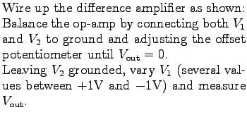
- Calculate the average gain of the amplifier. In this measurement, which
components determine the gain of the amplifier? How does the measured value
compare with the theoretical one?
- Connect
 to a constant +1V source and repeat the above two steps.
- Connect both
 and to the same variable voltage source;
measure
and to the same variable voltage source;
measure  for several values of
  between
  V and
V and  V.
V.
- Plot vs.
 and determine the value of the common mode
gain from the plot.
and determine the value of the common mode
gain from the plot.
- Interpret your data in terms of the imbalance of the resistance ratios of the
two pairs of resistors determining the gain, for the inverting and for the
non-inverting input. Which pair has the higher gain and by how much?
How could this common mode gain be reduced?
- Calculate the common-mode rejection ratio (CMRR) for your difference
amplifier. Calculate the maximum common-mode signal the amplifier can accept
if a 100 mV signal is to be amplified with an error of less than 0.1%.
Next: Instrumentation amplifier
Up: Advanced op-amp designs
Previous: Op-amp differentiator
For info, write to: [email protected]
Last revised: 2007-01-05