|
IDE877 PIC lab
The IDE877 PIC lab was developed as a tool to teach microcontoller programming
and interfacing. It was also intended to be used as a convenient way to implement some microcontroller
based projects. The IDE877 integrated development environment (IDE) is specific to the
Microchip PIC16F877 8-bit microcontroller. The following design criteria were followed:
- The system should consist of a PIC-based board that includes several basic peripherals and
a prototyping are for user projects. Software running on a host computer would be used to
program the PIC, interact with the user program and monitor the PIC status via a serial/USB interface.
- The programming language used to code the assembler, graphical user interface and access
to the PIC board should be platform-independent and freely available.
- The IDE should be intuitive and easy to use. The student should be able to type
in a PIC instruction, press a GO button and immediately observe changes to the PIC board
and the internal state of the microcontroller.
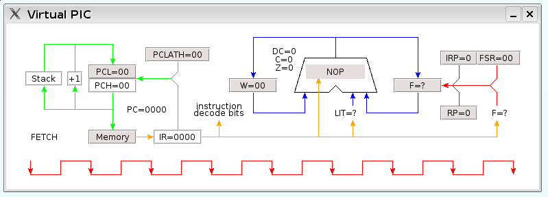
- The IDE simulator should further display the internal operation and data flow of the PIC on a
cycle by cycle basis, a 'virtual PIC', for educational purposes.
- The PIC instruction set should be small and need only include the basic arithmetic/logical
operations represented by gates, latches and timers. The focus here is not on
computer programming.
- The PIC should be pre-programmed with a library of subroutines that make the use of the
PIC board hardware such as LCD displays and A/D converters transparent to the user.
- The PIC board should be able to operate as a stand-alone data acquisition unit. The data
should be stored in a table that can be uploaded to the host computer on re-connection.
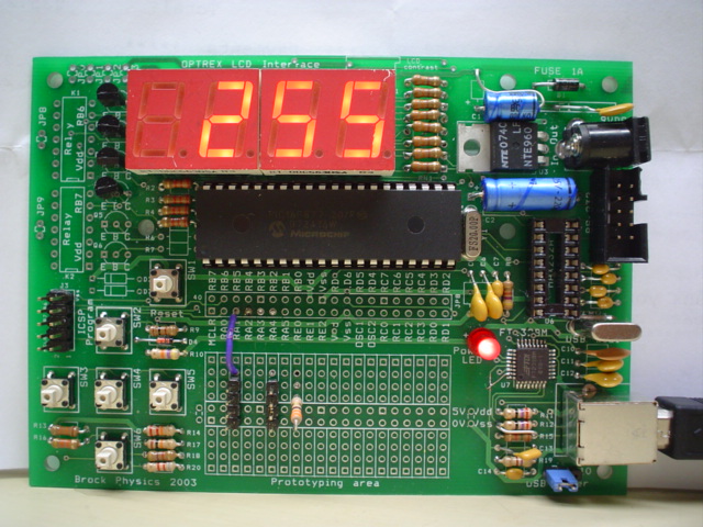
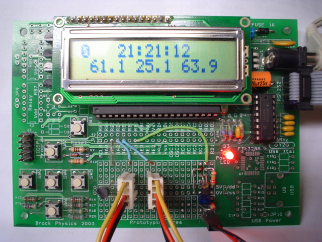
The hardware consists of a printed circuit board that houses the PIC,
LED/LCD displays, a keypad, solid state relays, serial RS232 and USB interface.
The PIC microcontroller includes input/output ports, 8 channels of analog to digital
conversion, several counter/timers, and I2C/SPI bus interfaces to serial-connected
peripherals. The In-circuit serial programming port is used to load the PIC with a small
operating system that includes several preprogrammed input/output and data
conversion routines as well as tabular data storage in program memory.
PIC board: USB powered with LED display and self-powered serial-comnnected with LCD display:
The software is a platform independent TCL/TK script that codes the (mostly)
MPLAB compatible macroassembler, graphical user interface and PIC simulator.
When connected to the PIC board, the software uploads the user program and reads the
internal state of the PIC. With some hardware exceptions, the execution of code
by the simulator and the PIC yields identical results. These results can be displayed
on windows that monitor the state of file registers, EEPROM and program memory, user
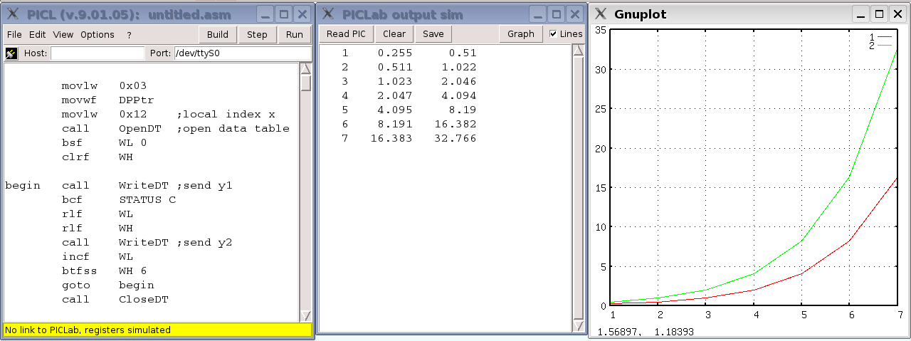
variables and data generated by the user program. A patch to the Gnuplot graphing
program allows the user program to control a window on the host machine
and hence provide real time graphical output of the user data.
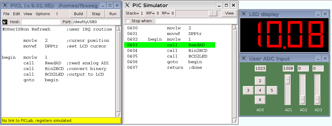
Simulated LED output:
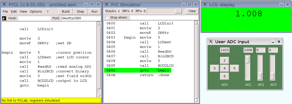
Simulated LCD output:
Virtual PIC output window and tutorial as a PDF file
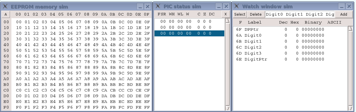
PIC/simulator EEPROM, status and watch windows:
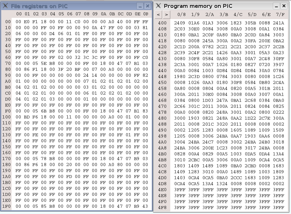
PIC/simulator program and file memory windows:
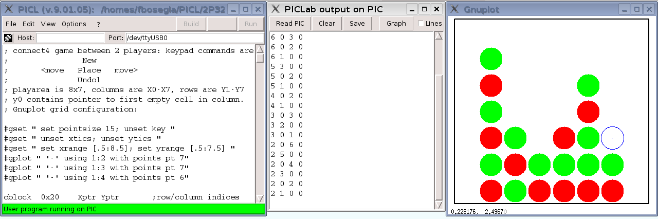
PIC/simulator output to Gnuplot
Connect-4 game running on PIC with real-time output to Gnuplot:
IDE877 help menus as a PDF file
Some IDE877 student projects
The development team,
my official web page
and E-mail: fbosegla@brocku.ca
|